GD&T symbols tell you how much a part’s geometry can vary while still meeting its design requirements. These symbols help you communicate requirements for shape, alignment, and location on engineering drawings. This guide explains their meanings and shows you how to read them through a reference chart and practical drawing examples.
What Is GD&T?
GD&T, also written as GD and T, stands for Geometric Dimensioning and Tolerancing, a standardized system for specifying allowable geometric variation on engineering drawings and digital models. You use it to define requirements for a feature’s form, orientation, location, profile, and runout.
Dimensional tolerance symbols, such as ±, specify size limits. Size tolerances define how large or small a feature can be. For example, a hole specified as ⌀10 ±0.05 mm has an allowable diameter of 9.95–10.05 mm. A position tolerance separately controls where the hole’s axis may lie relative to the specified datums. Meeting the diameter requirement alone does not guarantee that the hole meets its position requirement.
Unless stated otherwise, this guide follows ASME Y14.5-2018, one of the main geometric tolerancing standards. If your drawing specifies another edition or ISO GPS standards, follow those requirements, as some definitions and default rules differ.
GD&T Symbols Chart and Meanings
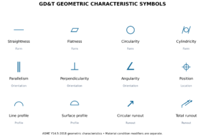
Use this GD&T symbols chart to identify the geometric control, what it limits, and whether it needs a datum reference. The table covers the 12 geometric characteristic symbols used in ASME Y14.5-2018. Read each symbol together with its tolerance value, modifiers, and attachment to the controlled feature.
| Symbol | Name | What It Controls | Datum Requirement | Example |
| ─ | Straightness | Surface line element or derived median line straightness. | No | Shaft or guide surface |
| ▱ | Flatness | Surface form between parallel planes; also applicable to a derived median plane. | No | Mounting face |
| ○ | Circularity (Roundness) | Roundness of individual circular elements. | No | Turned shaft cross-section |
| ⌭ | Cylindricity | Overall cylindrical surface form. | No | Precision bore |
| ∥ | Parallelism | Orientation parallel to a datum. | Yes | Sliding guide face |
| ⊥ | Perpendicularity | Orientation at 90° to a datum. | Yes | Bore relative to mounting face |
| ∠ | Angularity | Orientation at a specified basic angle. | Yes | Angled mounting face |
| ⌖ | Position | Location and applicable orientation of an axis, center plane, or center point. | Usually; certain patterns may omit datums. | Bolt-hole pattern |
| ⌒ | Profile of a Line | Individual line elements relative to the true profile. | Depends on control. | Curved cross-section |
| ⌓ | Profile of a Surface | Entire specified surface relative to the true profile. | Depends on control. | Contoured housing |
| ↗ | Circular Runout | Each circular element during rotation about a datum axis. | Yes | Shaft journal |
| ⌰ | Total Runout | Entire controlled surface during rotation about a datum axis. | Yes | Bearing seat |
For profile tolerances, datum references establish orientation and location when those relationships need to be controlled. Without datums, profile generally controls form.
Types of GD&T Symbols
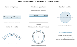
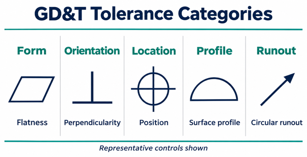
Geometric dimensioning and tolerancing symbols fall into five groups. These tolerancing symbols define zones that limit different types of geometric variation.
Form Tolerances
Form tolerances control a feature’s shape without datum references. The GD&T straightness symbol identifies a form tolerance that limits a surface line element between two parallel lines; flatness limits a surface between two parallel planes. Circularity uses two concentric circles for each circular element, while cylindricity uses two coaxial cylinders for the entire cylindrical surface.
You might use flatness on a sealing face or cylindricity on a precision bore.
Orientation Tolerances
Parallelism, perpendicularity, and angularity control alignment relative to a datum. For a planar surface, the tolerance zone consists of two parallel planes at the required orientation. An axis may use a cylindrical zone when a diameter symbol is specified.
For example, perpendicularity can keep a bore axis square to a mounting face. These controls establish orientation, not location.
Position Tolerance
Position controls where a hole, pin, or slot is located, including its applicable orientation. Basic dimensions establish the exact target location.
A typical hole-axis requirement uses a cylindrical tolerance zone; a slot’s center plane typically uses two parallel planes. You can use position on a bolt-hole pattern to control alignment with a mating part.
Profile Tolerances
Line profile controls individual cross-sectional contours; surface profile controls an entire specified surface. The tolerance zone follows the theoretically exact profile and is normally equally disposed on either side.
You can use profile on curved housings or mould surfaces. Datum references allow it to control orientation and location as well as form.
Runout Tolerances
Runout controls surface variation during rotation about a datum axis. Circular runout evaluates each circular element independently; total runout evaluates the entire controlled surface together.
For radial control of a cylinder, their zones are bounded by concentric circles and coaxial cylinders, respectively. Typical applications include shaft journals and bearing seats.
Older drawings: Concentricity and symmetry were removed from ASME Y14.5-2018 but may appear on earlier drawings. Follow the specified edition and obtain design approval before replacing these controls.
GD&T Drawing Example: A Machined Plate with a Hole Pattern
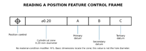
This GD&T example shows how geometric tolerances work together on an 80 × 60 × 10 mm plate with four mounting holes. Each hole must meet both its diameter limits and its position requirement.
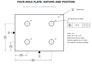
The drawing specifies:
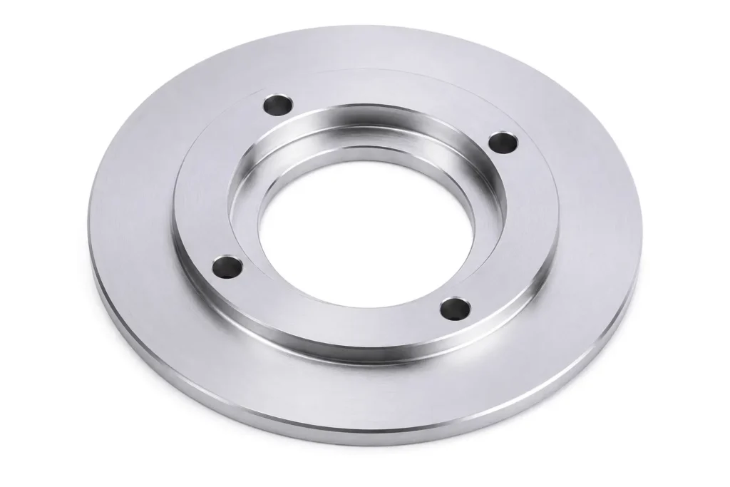
- Hole size: Four through-holes, each ⌀8.00–8.10 mm.
- Datum references: A is the broad mounting face, B the left edge face, and C the bottom edge face.
- Basic dimensions: Hole centers are located 20 or 60 mm from B and 15 or 45 mm from C.
- Position: ⌖ | ⌀0.20 | A | B | C.
The position requirement places each hole axis within a cylindrical zone 0.20 mm in diameter at its basic location. No material condition modifier is specified, so the position tolerance remains constant regardless of hole size.
For a simplified calculation, assume each measured hole axis is straight and perpendicular to datum A. The diametrical position error is:
Position error = 2 × √(ΔX² + ΔY²)
| Hole | Measured Diameter | X Deviation | Y Deviation | Position Error | Result |
| H1 | 8.05 mm | +0.03 mm | +0.04 mm | 0.10 mm | Passes both |
| H2 | 8.06 mm | +0.08 mm | +0.08 mm | 0.226 mm | Fails position |
| H3 | 8.12 mm | 0.00 mm | +0.03 mm | 0.06 mm | Fails diameter |
| H4 | 8.04 mm | −0.02 mm | +0.02 mm | 0.057 mm | Passes both |
H2 shows why hole size alone is insufficient: its diameter is acceptable, but its position error exceeds 0.20 mm. H3 has the opposite problem—it meets position but is oversized. The plate therefore fails the stated requirements.
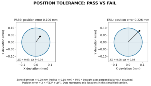
In actual inspection, evaluate the controlled axis over the hole’s length relative to the datum reference frame; a single center measurement cannot establish full compliance.
Why Is GD&T Important in Manufacturing?
GD&T helps you translate a part’s functional needs into clear manufacturing requirements. It matters for three reasons:
- Fit and function: It controls feature relationships that affect assembly, sealing, alignment, and movement.
- Consistent interpretation: Defined tolerance zones and datum references give design, manufacturing, and inspection teams a common basis for evaluating parts.
- Practical tolerances: You can control critical features according to their function while allowing more variation elsewhere, avoiding unnecessary machining and inspection costs.
Practical Applications of GD&T
You can use GD&T to communicate geometric requirements across engineering drawings, manufacturing, and inspection.
Engineering Drawings
GD&T symbols specify acceptable geometric variation on a drawing. They help you communicate requirements for feature shape, alignment, and location without relying on lengthy written notes.
CNC Machining
GD&T tolerance requirements help your manufacturing team plan workholding, setup references, and machining operations. For example, a position tolerance identifies how accurately mounting holes must be located relative to specified datums.
3D Printing
GD&T defines requirements for critical features on printed parts, including mating surfaces and locating holes. Depending on the process capability, some features may need machining after printing to meet those requirements.
Inspection and Quality Control
Inspectors use GD&T callouts to establish measurement references and evaluate whether features meet their tolerance zones. CMMs, dial indicators, and other suitable instruments provide the measurements needed for acceptance. Review YD Rapid’s quality assurance process when defining your inspection requirements.
Common GD&T Mistakes to Avoid
When interpreting engineering tolerance symbols, watch for these common mistakes:
- Treating position tolerance as separate ± coordinate limits.
- Confusing flatness with parallelism, or circularity with runout.
- Choosing datum features that do not reflect how the part functions.
- Specifying tighter tolerances than the part needs.
Check each callout against its intended function to avoid incorrect inspection and unnecessary manufacturing costs.
FAQs
Can GD&T Requirements Be Included in a 3D Model?
Yes. You can include geometric tolerances, datum identifiers, and other annotations as product manufacturing information (PMI) in a 3D model. Confirm that your supplier’s software can read this information and agree on which document governs if a drawing and model differ.
Does Every Feature Need a GD&T Callout?
No. Apply geometric controls where they are needed to define functional requirements. Other features may be adequately specified by size dimensions, general tolerances, and drawing notes.
Can You Inspect GD&T Requirements with Calipers Alone?
Generally, no. Calipers can check many sizes, but they cannot fully verify most geometric tolerances. The inspection method must suit the control, datum requirements, tolerance, and feature geometry.
What Should You Do If a GD&T Callout Is Unclear?
Ask the drawing owner to clarify it before manufacturing. Identify the affected feature and the specific ambiguity, then obtain an approved correction or documented clarification.
Do GD&T Requirements Apply Before or After Surface Treatment?
Check the drawing notes and specified standard. Plating or coating can change feature size and geometry, so clarify the required final condition and any masking requirements before production.
Conclusion
Understanding GD&T symbols helps you communicate geometric requirements and avoid machining, inspection, and assembly errors. You can specify tolerances that meet your needs without unnecessary costs. Send your drawings, CAD models, and inspection requirements to YD Rapid to discuss your CNC project and receive a quotation based on your specifications.