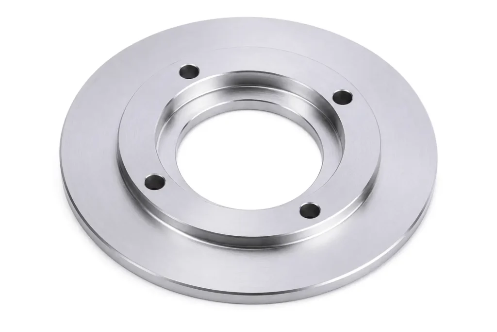
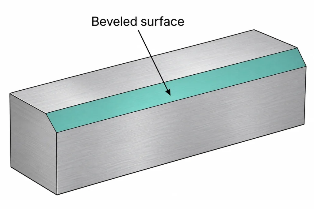
A beveled edge is a sloped surface along the edge of a part. You can use it to prepare a weld joint, guide parts during assembly, or form a cutting edge. Its angle and size depend on the function you need. This guide explains bevel types, their relationship to chamfers and fillets, and how you can specify, machine, and measure them.
What Is a Bevel? Definition and Basic Geometry
A bevel is an inclined surface along the edge of a workpiece. In cross-section, you see a straight, sloping line where the edge would otherwise have a square profile. A beveled edge is defined by its angle relative to a reference face and by its extent. You can select these dimensions to suit your part’s function; the angle does not have to be 45°.
For example, you might bevel the edge of a steel plate to prepare it for welding or the end of a shaft to help guide it into a mating hole. On a cylindrical part, the beveled surface can be conical, even though its cross-section appears straight.
What Is Beveling?
Beveling is the process of creating that inclined surface. In metal machining, you remove material by milling, turning, grinding, or another suitable cutting method. Bevel names the feature; beveling names the operation. Bevelling and bevelled are the British English spellings.
What Are the Common Types of Bevels?
Bevels are often described as single, double, or compound, depending on their cross-sectional profile. However, these names need context: a bevel on a cutting blade serves a different purpose from an edge prepared for welding.
Single Bevel
A single bevel has one inclined face along the edge. You can use this profile on a machined component where you need an angled transition or on a blade sharpened from one side.
In welding, a single-bevel groove joint has one prepared member facing another member with a square edge. If both mating edges are beveled to form a V-shaped opening, the joint is described as a single-V groove joint.
Double Bevel
A double bevel generally involves inclined faces on both sides, but their arrangement depends on the application.
On a cutting blade, you can grind both sides so the bevels meet at the cutting edge. In welding, a double-bevel groove preparation involves preparing an individual member from both sides of its thickness. This arrangement can provide welding access from both sides of the joint. If both mating members receive corresponding preparations, the joint may form a double-V groove.
Compound Bevel
A compound bevel combines two or more angles within an edge profile. Instead of following one continuous slope, the cross-section changes angle.
On a cutting tool, you might use a primary bevel with a narrower secondary bevel near the cutting edge. In thick-section weld preparation, a compound profile can provide access near the root while limiting the amount of material removed farther from it.
When you specify a bevel, include its cross-section, dimensions, and angle references. A name such as “double bevel” alone does not fully define the geometry you need.
The following sections show two separate naming contexts. Blade profiles describe the cutting edge; weld preparations describe the opening between joining members.
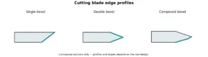
Cutting blade profiles. Teal lines identify the illustrated ground bevel faces.

Weld preparations. These are not blade profiles or dimensioned welding instructions.
TWI distinguishes single and double bevel preparations from V preparations; use the specified joint cross-section rather than a name alone.
Bevel vs. Chamfer vs. Fillet: What Is the Difference?
When you compare bevels and chamfers, both can have a straight, inclined cross-section, and their terminology can overlap. A fillet creates a rounded transition. Focus on the geometry and function rather than the name alone.
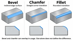
| Feature | Bevel | Chamfer | Fillet |
| Cross-sectional shape | Straight, inclined profile | Straight cut across a corner | Rounded transition |
| Typical uses | Weld preparation, cutting edges, and angled edge features | Assembly lead-ins, edge breaks, and clearance | Smooth transitions at shoulders, corners, and intersecting surfaces |
| How you specify it | Angle and dimensions relative to reference surfaces | Two distances, or a distance and angle | Radius, with additional requirements where needed |
A chamfer is not limited to 45°, and size alone does not distinguish it from a bevel. In mechanical design, “chamfer” commonly describes a corner-removal feature, while “bevel” is used more broadly for inclined edges. The same feature may be described using either term. Autodesk’s CHAMFER documentation supports both two-distance and distance-and-angle definitions.
To communicate your requirements clearly, specify the geometry on your drawing. Use dimensions and an angle for an inclined transition, or a radius for a rounded one.
How Are Bevels Used in Engineering?
You can use a bevel to provide welding access, guide mating parts, form a cutting edge, or change a product’s edge profile. Its angle and dimensions depend on the job it needs to perform.
Weld Preparation
For welding, you can prepare one or both joining edges to give the process access to the joint root and space for weld metal. Select the profile according to material thickness, welding process, and access from one or both sides. TWI’s weld preparation guide explains the relationship between groove access, root gap, and weld volume. A bevel alone does not guarantee full penetration or a sound weld.
Part Assembly and Clearance
A beveled entry on a shaft, pin, or hole can help you guide mating parts into position. An inclined edge can also provide clearance where an adjacent component would otherwise interfere with a corner.
You still need to check the mating geometry: removing too much material can reduce the contact area or locating length needed for the assembly.
Cutting Edges
On knives, blades, and cutting tools, bevels help form the cutting edge. You select the profile to balance cutting performance with edge support. A thinner edge may cut more easily but can be more vulnerable to damage; the suitable geometry depends on the tool material and what you are cutting.
Product Edges and Appearance
You can add a bevel to a housing, panel, or exposed component to create a defined border or a visible transition between surfaces. Removing an exposed square corner may also improve handling.
However, the new intersections can still be sharp or carry burrs. If the edge will be touched during use, specify the required edge condition as well as the bevel dimensions.
Why Is Beveling Important in Manufacturing?
A defined bevel gives you an edge feature that can be reproduced and inspected. This matters when assembly, welding, or finishing depends on consistent geometry across a batch.
These benefits come with tradeoffs. Beveling adds machining time and inspection work, and difficult-to-reach edges may require another setup. Removing excessive material can reduce wall thickness, shorten a locating surface, or leave a thin edge vulnerable to deformation and damage.
Specify the bevel your part needs, with tolerances that match its function. A cosmetic edge and a weld preparation do not require the same controls. Clear requirements help you achieve the intended result without adding unnecessary manufacturing cost.
How Are Bevels Made?
When beveling metal, you can use milling, turning, grinding, or dedicated beveling equipment. The suitable method depends on the workpiece shape, material, edge accessibility, and required accuracy.
Bevel cutting describes the material-removal operation. A bevel cut on a plate may prepare a joining edge; a beveled cut on a sleeve may form a conical transition. Your drawing defines the finished profile, regardless of the cutting method.
CNC Milling
CNC milling is suitable for bevels on blocks, brackets, housings, and contoured parts. You can use an angled cutter when its geometry matches the required bevel, or machine the surface with an end mill and a suitable toolpath. Some features require an angled setup or multi-axis positioning to give the tool access.
Workholding and tool clearance matter, especially near thin walls, deep pockets, or adjacent features.
CNC Turning
CNC turning is suitable for bevels on rotational parts such as shafts, sleeves, rings, and pipe ends. As the workpiece rotates, the cutting tool moves along a programmed path to create the inclined profile. A bevel around a cylindrical part typically forms a conical surface.
You can often machine an accessible bevel in the same setup as the surrounding diameters and end face, helping maintain their dimensional relationship.
Grinding
Grinding can produce or finish bevels on hardened components, blades, and cutting tools. You may choose it when the material is difficult to cut conventionally or when the edge requires a controlled finish.
Wheel selection, cooling, and process settings need attention. Excessive heat can damage the surface or affect the properties of a heat-treated cutting edge.
Dedicated Beveling Equipment
Dedicated machines are commonly used to prepare plate edges and pipe ends for welding. Depending on the equipment, they remove material with rotating cutters or abrasive tools. Portable units can work on large components that are difficult to bring to a machining center.
When selecting equipment, check its supported bevel angles, material thickness range, clamping requirements, and ability to leave the specified root face.
How Do You Specify a Bevel on a Drawing?
To specify a bevel clearly, show its location, angle, and size. A section view is useful when the profile is difficult to see in the main views. The word “bevel” alone does not provide enough information to manufacture or inspect the feature. Use consistent engineering drawing symbols for dimensions, tolerances, and surface requirements.
Define the Angle and Reference Face
The angle of bevel must be measured from a clearly identified reference surface. Show that reference on your drawing. An angle measured from the top face differs from one measured from a plane perpendicular to that face, unless both are 45°.
For weld preparations, distinguish the bevel angle on an individual member from the included groove angle between mating members. A pipe bevel angle should identify its reference as well; do not assume it is measured from the pipe axis or end face without checking the drawing.
Dimension the Bevel Size
State whether your dimension represents a distance along an adjacent face, the depth through the material, or the actual sloping face width. These measurements are different and should be clear from the dimension lines.
If the remaining material is important, specify the required wall thickness or root face. Avoid adding redundant dimensions that could conflict with each other.
Add Tolerances and Surface Requirements
Apply size and angular tolerances that match the bevel’s function. You should also state any necessary surface texture or burr-removal requirements. Where general drawing tolerances apply, make sure they adequately control the feature.
Simple Drawing Example
For an external bevel on a rectangular block, your section view could specify:
| Drawing requirement | Example |
| Reference surface | Top face |
| Bevel angle | 30° ±0.5° to the top face |
| Bevel extent | 2.0 ±0.1 mm measured along the top face from the theoretical sharp corner |
| Edge condition | Remove burrs |
Here, the 2.0 mm dimension is the distance along the top face, not the sloping face width. The example values are illustrative; choose tolerances and any surface texture requirement according to your part’s function.
How Are Bevels Measured?
You need to check both the bevel angle and its dimensions. A correct angle does not guarantee the correct size, and a width measurement alone cannot confirm the full profile. Start by identifying the reference surface and measurement directions shown on your drawing.
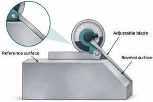
Checking the Angle
For accessible, straight edges, you can use a suitable bevel protractor to measure the angle relative to the specified face. For example, Mitutoyo’s Series 187 universal bevel protractor uses a graduated scale and a vernier for angle measurement. Check the specific instrument’s accuracy and suitability for your tolerance. An adjustable bevel gauge can transfer or compare an angle, but it does not provide a numerical reading by itself.
For small features or tighter tolerances, an optical comparator or vision measuring system can evaluate the cross-sectional profile where it is visible. A coordinate measuring machine (CMM) can measure accessible bevel surfaces and calculate their angle relative to the reference geometry, provided the feature is large enough for suitable probing.
Checking the Dimensions
Check whether the drawing specifies a distance along an adjacent face, the bevel depth, or the sloping face width. Measure that dimension directly where practical; these values are not interchangeable.
Calipers may be suitable for accessible, relatively large features with moderate tolerances. Narrow bevels and dimensions referenced to a theoretical sharp corner often require optical measurement or a CMM to reconstruct the intersection of the adjacent surfaces. For weld preparations, a suitable weld preparation gauge can also check features such as the bevel angle and root face.
Choosing the Measurement Method
| Bevel feature | Suitable inspection approach |
| Accessible straight bevel | Bevel protractor for angle; suitable dimensional tools for size |
| Small, visible profile | Optical comparator or vision measuring system |
| Precision bevel with defined reference geometry | CMM, where probe access and feature size permit |
| Plate or pipe weld preparation | Weld preparation gauge matched to the specified features |
Before inspection, clean the reference surfaces and remove loose burrs that could affect contact. On long edges or circular parts, check multiple locations to assess consistency. Choose equipment with sufficient accuracy for the specified tolerance and a setup that references the same geometry as the drawing.
FAQs
Can You Add a Bevel to an Existing Part?
Yes, if the part has enough material and the edge is accessible. Before reworking it, check whether material removal will affect nearby features, protective coatings, or mating dimensions.
Should You Machine a Bevel Before or After Coating?
You will usually machine it before coating so the newly exposed surface receives protection. If you bevel a coated part afterward, the exposed area may need refinishing. Your drawing should clarify whether critical dimensions apply before or after coating.
Can Plastic Parts Have Beveled Edges?
Yes. You can machine bevels into plastic parts, but the material affects the process. Soft plastics may deform or leave burrs, while brittle plastics may chip. Thin edges also need adequate support during machining.
Does a Bevel Change the Nominal Size of a Part?
A local edge bevel can leave the main outside diameter, length, or width unchanged while reducing the full-size bearing or locating area near the edge. When you revise a part, check where its nominal dimensions are taken and whether the mating component needs an uninterrupted contact surface.
Is a Countersink the Same as a Bevel?
A countersink is a conical recess at a hole opening, commonly used to seat a countersunk screw head. It has a beveled profile, but you should specify it as a countersink when that seating function matters, including the required diameter and included angle.
Conclusion
Choose a bevel profile based on what your part needs to do, whether that is preparing a weld joint, guiding assembly, or forming a cutting edge. Specify the angle, reference face, dimensions, and relevant tolerances on your drawing. Clear requirements help your manufacturer select a suitable machining method and verify that the finished bevel meets your design.
For custom machined parts, send YD Rapid your CAD model, drawing, material, quantity, and finish requirements when you request a quote. Identify any bevel angles or edge dimensions that need inspection.