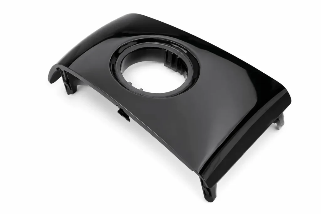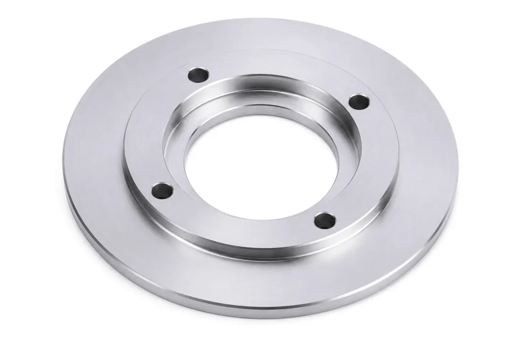
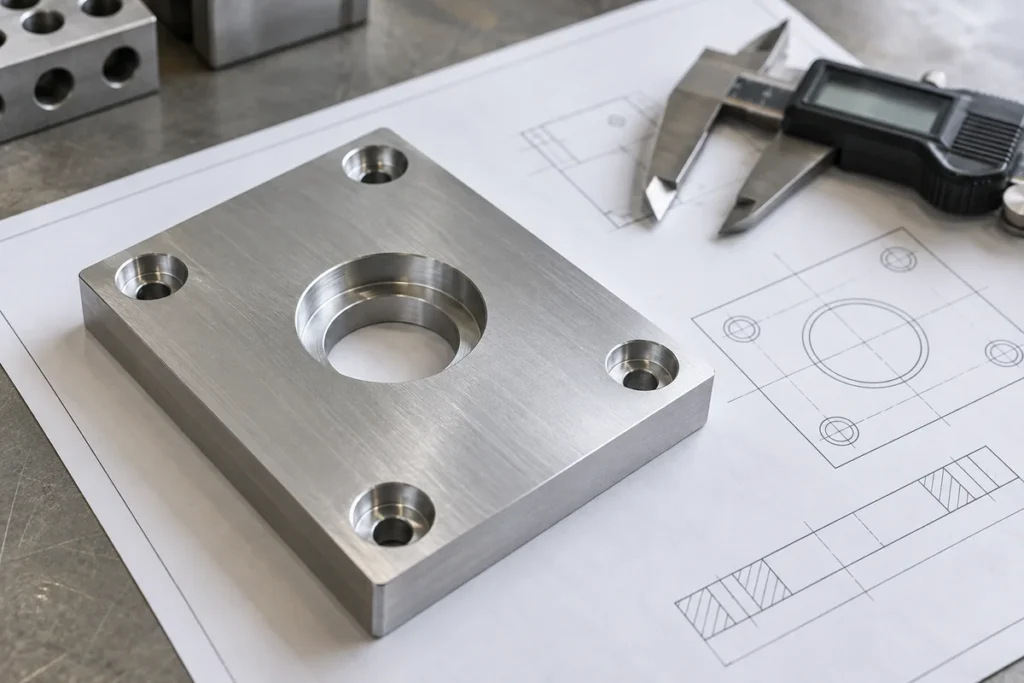
When you read a CNC part drawing, engineering drawing symbols specify sizes, holes, threads, geometric tolerances, and surface texture. Misread a depth callout or datum reference, and your part may fail inspection or assembly.
This guide gives you a quick-reference chart, practical explanations, and a CNC part example to help you identify requirements and resolve ambiguities before CNC machining.
Engineering Drawing Symbols and Meanings
Use this chart to identify common mechanical engineering drawing symbols. Examples use millimeters unless stated otherwise.
| Symbol or notation | Name | Meaning and example |
| ⌀ | Diameter | Circular feature diameter: ⌀10 means 10 mm. |
| R | Radius | Arc radius: R3 means 3 mm. |
| ↧ | Depth | Feature depth: ⌀6 ↧12 indicates a 6 mm hole, 12 mm deep. |
| ⌴ | Counterbore | Cylindrical, flat-bottomed recess; requires diameter and depth. |
| ⌵ | Countersink | Conical recess; requires opening diameter and included angle. |
| M | Metric thread | M6 × 1–6H specifies an internal metric thread. |
| ± | Bilateral tolerance | 20 ±0.1 permits 19.9–20.1 mm. |
| ▱ | Flatness | Controls surface form without a datum reference. |
| ∥ | Parallelism | Controls orientation relative to a datum. |
| ⊥ | Perpendicularity | Controls a 90° relationship to a datum. |
| ⌖ | Position | Controls feature location through a defined tolerance zone. |
| Ra | Roughness parameter | Ra 1.6 µm specifies a surface texture requirement. |
| THRU | Through | Feature extends through the part’s thickness. |
| REF | Reference | Informational dimension, not an independent acceptance requirement. |
Read these technical drawing symbols with their dimensions, notes, and attachments. Request a corrected drawing if a symbol is illegible.
Check the Drawing Standard, Units, and Projection First
Start with the title block. Confirm the drawing number, revision, material, units, and governing standards. Similar-looking symbols can follow different rules under ASME and ISO, so use the specified edition.
Check whether dimensions use millimeters or inches. A diameter of 0.250 inch equals 6.35 mm, whereas 0.250 mm describes a much smaller feature.
Next, identify the projection system. Use the drawing’s projection symbol, not the supplier’s country, to interpret view placement.
| View | First-angle projection | Third-angle projection |
| Top view | Below the front view. | Above the front view. |
| Right-side view | Left of the front view. | Right of the front view. |
Review general tolerances and notes before reading individual callouts. A stated individual tolerance overrides the applicable general tolerance for that dimension. Basic and reference dimensions have different roles and should not automatically receive a general ± tolerance.
Also confirm that your 2D drawing and 3D model represent the same revision. Resolve discrepancies before production, and use stated dimensions rather than measuring a scaled PDF image.
Dimension, Hole, and Thread Symbols Explained
Machining blueprint symbols work together in complete callouts. For example, 4X ⌀6.6 THRU identifies four nominal 6.6 mm through-holes. Other dimensions and tolerances define their locations and acceptance limits.
Distinguish these recessed features:
- Counterbore: A cylindrical, flat-bottomed recess, commonly used for a recessed fastener head. Check its diameter, depth, and entry face.
- Countersink: A conical recess, commonly used for flat-head screws. Check its opening diameter and included angle.
- Spotface: A local flat seating surface, often on castings or forgings. Check the specified diameter and depth or cleanup requirement.
For threads, M6 × 1–6H means a nominal 6 mm internal metric thread, a 1 mm pitch, and a 6H tolerance class. A Unified designation such as 1/4-20 UNC-2B instead specifies nominal inch diameter, threads per inch, thread series, and internal thread class.
On blind tapped holes, full thread depth and drilled depth are separate requirements. Confirm whether the drill depth is measured to the drill point or the full-diameter portion. Tool geometry and clearance mean a deeper hole does not provide the same depth of usable thread.
How to Read GD&T Symbols and Feature Control Frames
Geometric Dimensioning and Tolerancing controls geometry beyond feature size. A hole can meet its diameter tolerance while failing its position requirement.
| Category | Common controls | What you evaluate |
| Form | Straightness, flatness, circularity, cylindricity. | Individual feature shape, without datum references. |
| Orientation | Parallelism, perpendicularity, angularity. | Orientation relative to a datum. |
| Location | Position. | Location within a defined tolerance zone. |
| Profile | Profile of a line or surface. | Deviation from a theoretically exact contour or surface. |
| Runout | Circular runout, total runout. | Surface variation during rotation about a datum axis. |
Read the Frame from Left to Right
Consider this simplified text representation:
Position | ⌀0.10 | A | B | C
The first compartment identifies position. The next defines a cylindrical tolerance zone 0.10 mm in diameter. A, B, and C establish primary, secondary, and tertiary datum priority. Basic dimensions locate the zone theoretically exactly.
For a straightforward hole-axis requirement, the axis must stay inside that zone. ⌀0.10 does not mean ±0.10 mm in X and Y, and it does not specify hole diameter tolerance.
A datum feature is an actual feature on your part; a datum is the theoretically exact reference established from it. Read priority from the frame: B | A | C is different from A | B | C. Form controls do not reference datums, and not every other frame needs three references.
Check Material Condition Modifiers
A circled M after a geometric tolerance specifies maximum material condition: the smallest permitted hole or largest permitted shaft. For applicable requirements, departure from MMC provides bonus tolerance.
A modifier following a datum reference instead affects the material boundary used to establish that reference. Its role differs from bonus tolerance on the controlled feature.
Concentricity and symmetry were removed from ASME Y14.5-2018 but may appear on older or differently governed drawings. Do not replace them without design approval.
Surface Finish Symbols and Roughness Requirements
Conventional surface texture symbols commonly use a check-mark-shaped form with optional modifications.
| Symbol variant | Meaning |
| Basic symbol | Neither requires nor prohibits material removal. |
| Added bar | Material removal is required. |
| Added circle | Material removal is prohibited. |
These symbols do not automatically prescribe milling, turning, or grinding. A roughness requirement can permit different processes depending on your material and geometry.
Ra describes the arithmetic mean of absolute profile deviations from the mean line over the evaluation length. Confirm whether values use micrometers or microinches: Ra 1.6 µm is approximately 63 µin. Read acceptance rules and measurement conditions with the value.
Follow the symbol’s attachment to identify the applicable surface. A local sealing-face requirement does not automatically apply to every face. Check general notes, lay direction, and whether requirements apply before or after treatment.
Roughness and flatness are separate. Roughness describes surface texture; flatness controls overall form between two parallel planes. Your surface can be smooth but bowed, or flat with pronounced machining marks. A functional mating face may need both requirements verified independently.
Line Types and Engineering Drawing Abbreviations
Line types distinguish geometry from references, helping you interpret symbols in mechanical drawings.
| Line type | Typical appearance | Meaning |
| Visible line | Continuous, relatively thick. | Visible edges. |
| Hidden line | Short dashes. | Concealed edges. |
| Centerline | Alternating long and short segments. | Axis, center, or symmetry reference. |
| Dimension line | Thin line with arrowheads. | Extent of a dimension. |
| Section lines | Thin diagonal lines. | Material intersected by a cutting plane. |
A centerline does not establish a datum by itself. Compare views or sections when overlapping lines obscure geometry.
Common abbreviations include THRU for through, REF for reference, TYP for typical, MAX/MIN for upper/lower limits, and PCD for pitch circle diameter.
Confirm the scope of TYP rather than applying it to every similar-looking feature. An explicit quantity such as 4X often communicates repeated requirements more clearly.
Worked Example: Reading a CNC Part Drawing
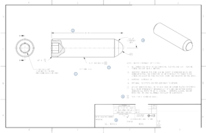
Practice blueprint reading with this screw drawing. Follow the six markers to interpret its views, machining symbols, dimensions, and inspection requirements.
1. Read the Section View
The arrows labeled A identify the cutting plane for SECTION A-A. Section hatching reveals material around the internal drive recess. Here, A-A is a section identifier—not a datum reference. You should not interpret these letters as the datum A used in a GD&T frame.
2. Apply the Stated Units and General Tolerance
The drawing specifies millimeters. Follow the extension lines for 25.00 rather than assuming it represents threaded length alone.
The title block assigns ±0.100 mm to two-decimal dimensions, subject to the drawing’s exceptions. The permitted range for this dimension is therefore 24.90–25.10 mm. Note 1 specifies that dimensions apply after finishing, plating, and heat treating.
3. Decode the External Thread
The callout 0.25-100 UNS-3A specifies a nominal 0.25-inch external thread with 100 threads per inch, a Unified Special thread series, and a class 3A tolerance. Although general dimensions use millimeters, this thread designation uses inch-based conventions.
Do not substitute a similar-diameter metric thread; pitch, form, and tolerance class must also match.
4. Read the Minimum Clearance Angle
The 135° CLEARANCE MIN callout establishes a minimum clearance angle at the indicated end geometry. It is not a countersink angle. Follow the leader to identify the controlled feature.
5. Check the General Surface Requirement
The title block shows a surface finish value of 1.6 with a conventional texture symbol. Read its parameter, units, scope, and acceptance rules under the referenced drawing conventions; the number alone does not explicitly spell out Ra or micrometers. Confirm those details with the drawing owner if needed.
6. Connect the Thread to Its Inspection Note
The boxed 6 beside the thread callout points to Note 6: “VERIFY WITH GO/NO-GO GAUGE.” It is a note reference, not a boxed basic dimension. Select the appropriate gauges for the specified external thread.
This drawing has no A/B/C datum system or position frame. Refer to the separate GD&T example for geometric controls.
Common Drawing Misinterpretations to Avoid
| Possible misreading | Actual meaning | Confirm before machining |
| Diameter as radius | ⌀ and R define different sizes. | Prefix and feature attachment. |
| Position as X–Y tolerance | The specified zone controls geometry. | Basic dimensions, datums, modifiers. |
| Flatness as parallelism | Flatness controls form without a datum. | Functional orientation requirements. |
| Drill depth as thread depth | Full thread and drilled depths differ. | Depth reference and usable thread. |
| Roughness as a mandatory process | Texture does not identify a unique process. | Separate process notes. |
| Newest file automatically governs | Document precedence needs agreement. | Revision and known discrepancies. |
Record clarification answers before machining.
What to Confirm Before Sending a Drawing for CNC Machining
Provide a consistent drawing package containing:
- Matching 2D and 3D files with drawing number and revision.
- Material grade, temper or condition, and required certificates.
- Current order quantity, with future volumes identified separately.
- Functional dimensions, fits, threads, datum features, and tolerances.
- Finishing specifications and masking requirements.
- Inspection scope, quality assurance requirements, and agreed acceptance procedures.
For coated or plated parts, clarify which dimensions apply after treatment. Resolve model and drawing differences with the design owner. Explaining a feature’s function helps discussion, but “critical feature” alone does not define an acceptance limit.
FAQs
Are There Any Software Tools That Help Create Engineering Symbols?
Yes. You can use CAD drawing tools such as SOLIDWORKS or Onshape to add geometric tolerances, datum identifiers, and surface finish symbols. Use built-in annotation tools and check your drafting standard. Correct symbol appearance alone does not guarantee correct values, references, or feature attachment.
How Can You Improve Your Technical Drawing Skills?
Create a drawing from a simple part, then ask someone to interpret it without your explanation. Record where they need clarification. Review those areas with a machinist or inspector, revise, and repeat. This develops manufacturing communication skills beyond memorizing symbols.
What Should You Look for in a Technical Drawing Course?
Choose a mechanical drawing course with practical exercises, instructor feedback, and relevant standards. Distinguish CAD operation from drawing interpretation and GD&T: you need more than software skills to specify manufacturable parts.
Conclusion
Read engineering symbols on drawings as complete requirements. Check standards, units, and revision, then connect dimensions, datums, tolerances, and texture to each feature.
To request a CNC machining quote from YD Rapid, send your current drawing, matching CAD model, material, quantity, and finishing requirements. Highlight unresolved callouts so they can be discussed before production.