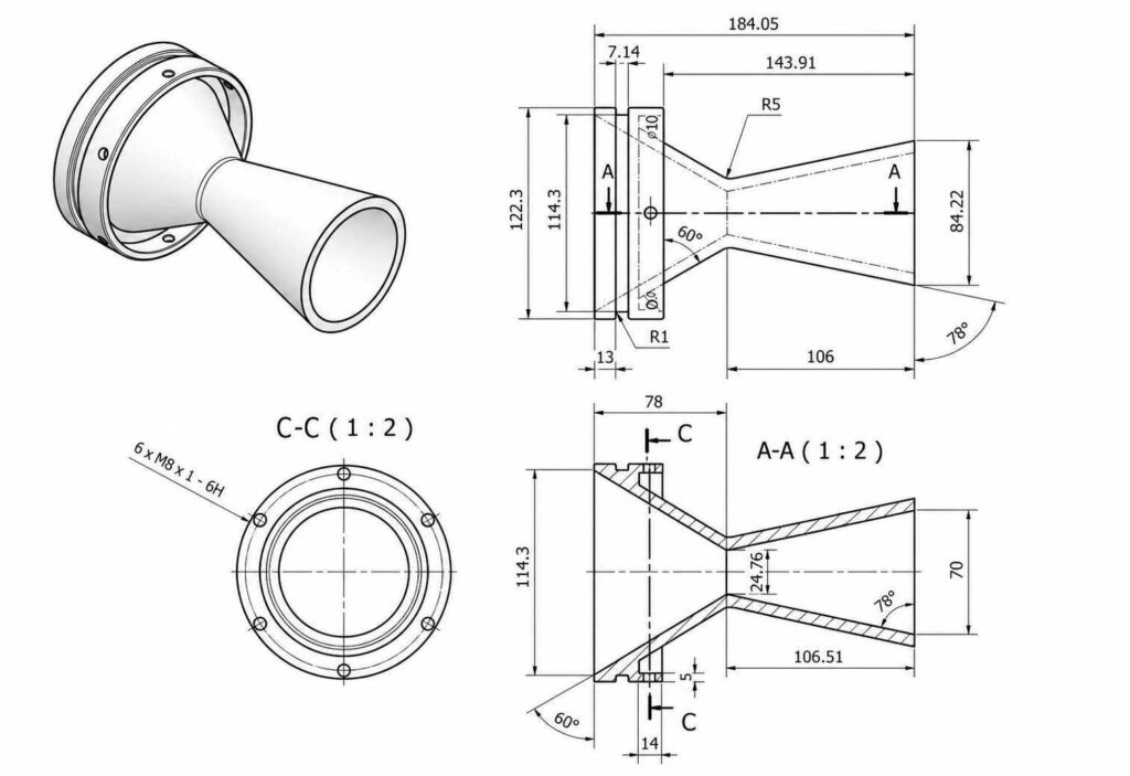
GD&T for CNC machining defines the allowable variation in a part’s form, orientation, location, and runout while ensuring that the finished component functions as intended.
Key Takeaways!
- GD&T defines and controls the form, location, orientation, and runout of CNC machined features beyond basic size dimensions.
- Datum references create a fixed inspection and machining reference system for complex parts.
- Position tolerances are commonly used for hole patterns, mounting features, and assembly locations.
- Proper GD&T selection helps control important features without adding unnecessary machining requirements.
- Clear GD&T drawings improve communication between design engineers, CNC programmers, machinists, and inspectors.
A CNC machined part is not defined only by its length, width, and hole sizes. Features such as mounting holes, sealing surfaces, bearing seats, and alignment faces often need to maintain a specific relationship with each other. A hole can meet its diameter requirement but still prevent assembly if its location shifts from the intended position.
Geometric Dimensioning and Tolerancing (GD&T) provides a way to control these relationships on engineering drawings. Instead of adding strict limits to every dimension, engineers define how much a feature can vary in position, shape, angle, and surface condition while still allowing the part to function correctly.
This guide explains GD&T symbols, tolerance types, datum concepts, and practical drawing examples used in CNC machining. It also covers how engineers apply GD&T requirements to create drawings that are clear for production and inspection teams.
What Is GD&T in CNC Machining?
GD&T (Geometric Dimensioning and Tolerancing) is a drawing system used to control how a machined feature is allowed to vary from its exact design condition. It defines requirements for feature size, location, shape, and alignment using standard symbols and tolerance zones.
Why Engineers Use GD&T Instead of Only Dimensional Tolerances
Dimensional tolerances limit the allowable variability in features such as a hole diameter or shaft diameter. They do not specify the precise position, direction, or contact necessary for assembly.
Take an example of a mounting plate that is CNC machined and has multiple bolt holes. They can be the right size for each hole, but if there is a slight error in the position of each hole, then the plate will not join with another component. This cannot be managed just by controlling the diameter tolerance.
The GD&T allows the engineer to manage the features that influence part function.
Common examples include:
- Locate holes and slots with respect to specified datums in position tolerances.
- Flatness is used to determine if a surface is within the allowable plane for good contact.
- Perpendicularity is used to determine whether features are properly aligned to a reference surface.
This method helps to prevent over-machining. The tighter the control that engineers can apply, the more restricted the feature has to be that acts on assembly, movement, sealing, or alignment.
How GD&T Improves CNC Drawing Communication
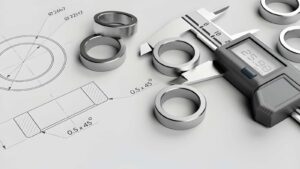
Drawings without GD&T are sometimes subject to interpretation. A note like “hole location +/- 0.05 mm” is not always clear on what the hole is supposed to be referencing. GD&T eliminates this uncertainty by employing datums and feature control frames.
This information can be useful in CNC machining for:
- Choosing appropriate workholding and setup references.
- Identifying areas that need more monitoring.
- Methods of planning inspection before Production.
Understanding the Main GD&T Concepts Used in CNC Drawings
GD&T drawings are more than dimensioned drawings, and determine the location, alignment, and control of a feature once the process has been completed. The three basic elements engineers and machinists must understand when reading a GD&T callout are feature control frames, datum references, and tolerance zones.
These elements are used to describe the way a part is to be set up, machined, and inspected.
Feature Control Frames
A feature control frame is a rectangular box that is employed to define a geometric requirement on a drawing. It specifies the control type to be used, the variation to be allowed, and which datums to use as references.
A typical position tolerance callout may look like:
⌖ ⌀0.05 | A | B | C
This means:
- ⌖ is the position tolerance control.
- The cylindrical tolerance zone has a diameter of ⌀0.05.
- A, B, and C indicate datum references. These are used to define the location of the feature.
If the hole diameter is one of the multiple mounting holes in a CNC-machined plate, the diameter influences the fit of the fastener. The position tolerance determines whether those holes are in the proper position relative to the assembly pattern or not.
Datum References and Their Role in Part Inspection
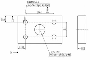
A set of datums defines the reference system for the production and checking of a part. They are the surfaces, axes, or points on which the location of features is determined.
Datums are typically chosen for CNC machining depending on the assembling process of the part or how it is mounted on a machine.
A typical datum setup consists of:
- Primary datum (A): The first surface used for support and the main orientation for the part.
- Secondary datum (B): A second surface that represents a second direction of movement.
- Tertiary datum (C): The last reference used to determine the final position.
For instance, the mounting face can be used as datum A for a machined gearbox housing. The side face can be datum B, and the end face can be datum C. The bearing bores and bolt holes are then found from this reference system.
This way, the machining set-up and inspection process remain standard. The same structure is applied from the drawing board to the last measurement.
Tolerance Zones in GD&T
The maximum deviation from the drawing size (tolerance zone) allows a region within a feature’s size. It is not just a +/- dimensional tolerance, but it is used to control a feature’s actual shape or position.
A hole, for example, is not free to move in the X and Y directions with a position tolerance. It should be aligned within a cylindrical tolerance zone of the theoretical position.
Some examples of the many tolerance zones include:
- Cylindrical Tolerance Zones: Applies to hole location, pins, or shafts. The feature axis should be contained within a specified cylinder.
- Surface tolerance zones: For flatness, profile, and surface control. The entire surface has to be within the limits indicated.
- Parallel and perpendicular zones: Used to specify the range of relationship between two features, e.g., a face that has been machined and a bore axis.
Common GD&T Symbols Used for CNC Machined Parts
GD&T symbols are used on CNC drawings when normal dimensions cannot fully describe the requirement of a feature. A hole, surface, or shaft may have the correct size but still cause assembly problems if its position, alignment, or shape is not controlled.
Engineers usually apply GD&T to features that affect how parts fit together or operate after machining. The most common controls include form, orientation, location, and runout tolerances.
Form Tolerances: Flatness, Straightness, Circularity, and Cylindricity
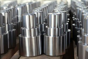
Form tolerances determine the form of a feature. Do not include a datum reference with them because they do not compare the feature with another surface.
Flatness: It is applied when the surface must be level over its whole area. For instance, if a mounting face has a flatness requirement to contact another part. Even if the surface dimension is met, it may not pass the test in relation to its size if there are too many high and low areas.
Straightness: It is used to determine whether a line or an axis is straight. It is frequently used in shafts, guideways, and long machined edges where bending and deviations can interfere with the movement.
Circularity: The circularity defines the extent to which a round feature is actually round. It is frequently used for holes, pins, and shafts where the shape influences the fit.
Cylindricity: It affects the entire shape of a cylindrical feature. It doesn’t measure just a cross-section of a shaft or hole, but the full surface. This control is utilized for precision bearing seats and rotating parts.
Orientation Tolerances: Parallelism, Perpendicularity, and Angularity
Orientation Tolerances: These are used to specify how one feature relates to another. These controls are necessary to make sure parts are properly aligned during assembly.
Parallelism: It is used to maintain a specified parallelism between two surfaces or features. Some machined guide surfaces, for instance, might require control of the parallelism to ensure smooth motion.
Perpendicularity: It is used to modify the angle of a feature relative to a reference surface, while maintaining the 90° angle. A properly sized drilled hole in a mounting block can be sized to fit a bolt or pin, but if the hole is not perpendicular, a bolt or pin may not fit properly.
Angularity: It controls features that are set at a given angle. It is often used when the angle makes a difference in the final assembly, as in angled faces, slots, and tapered features.
Location Tolerances: Position, Concentricity, and Symmetry
Location tolerances determine the placement of a feature on a part. These controls are commonly found on holes, slots, and cylindrical features made using CNC.
Position tolerance: This is the most frequently used location control used in CNC drawings. It sets a distance from the exact location of a feature that it may travel. For instance, if the bolt-hole pattern is such that each hole can have a slight variation, but within the position zone specified, then the mating part can be installed.
Concentricity: A control that determines whether two cylinder features have the same centre axis. This is applied to features like stepped shafts in which multiple diameters are to be rotated about a shared axis.
Symmetry: It is used to keep a feature the same on both sides of a central axis. It does not show up in the CNC drawings as much since position tolerance is more often the more practical method of controlling the location of the feature.
Runout Controls for Rotating Components
The most common applications of runout controls include rotation of parts like shafts, spindles,s and bearing components. They regulate the amount of deflection from their intended axis when rotated.
Circular runout: It measures one plane of a rotating surface. It is usually checked using a dial indicator as the part is turned around its datum axis.
Total runout: It is the entire surface through the length of the feature and takes into account the surface variation and alignment errors.
A 27mm diameter shaft, for example, can have a correct diameter, but cause vibration if it is not concentric. This type of problem can be partially regulated by runout requirements.
GD&T Position Tolerance for CNC Machined Holes
Position tolerance is mainly used for controlling the location of holes, slots, and other features that must match with another component. In CNC machining, the hole diameter can be correct, but the part can still fail during assembly if the hole location shifts.
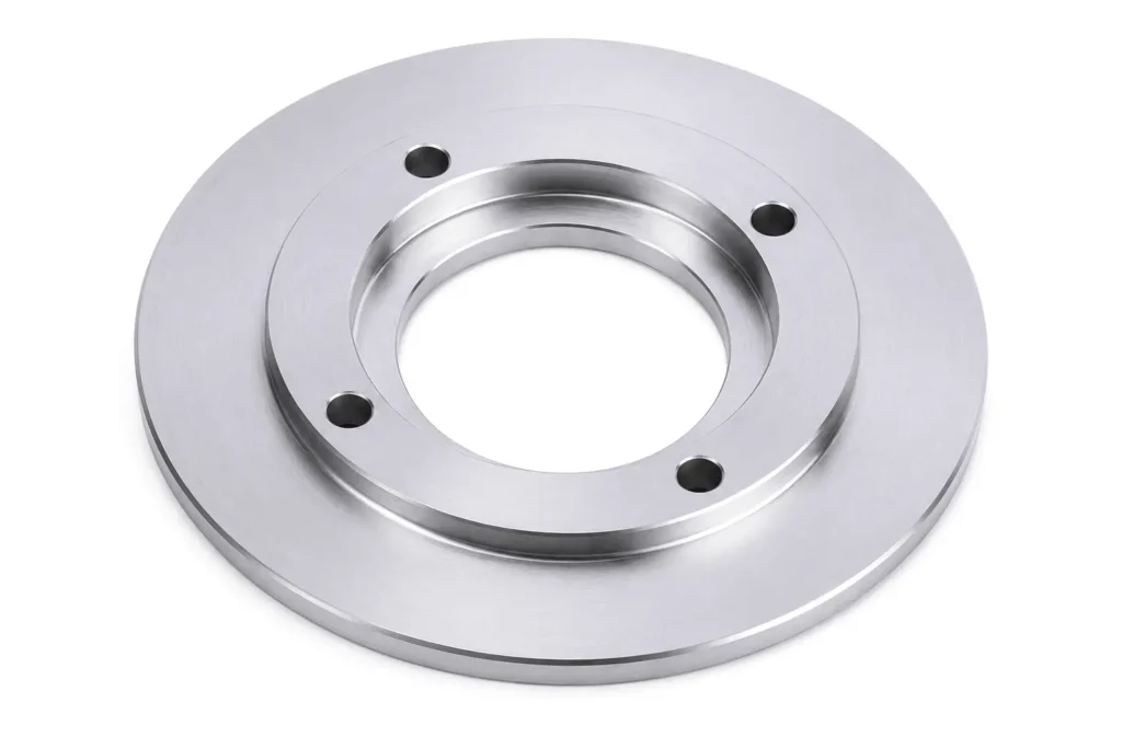
For example, a mounting plate may have four bolt holes. Each hole may measure exactly Ø10 mm, but a small location error can prevent the bolts from passing through the mating part. Position tolerance controls this location error by defining an acceptable zone around the intended hole centre.
Unlike traditional coordinate tolerances, position tolerance controls the complete location of the feature in relation to the datum reference system.
Reading a Position Tolerance Callout
A position tolerance callout tells the manufacturer three main things:
- Which feature is controlled
- How much the feature location can vary
- Which surfaces establish the measurement reference
A typical callout may look like:
⌀0.20 | A | B | C
The meaning is:
- The centre of the hole must remain inside a cylindrical tolerance zone with a diameter of 0.20 mm.
- Datum A establishes the primary reference surface.
- Datum B controls the secondary direction.
- Datum C defines the final location reference.
For CNC machining, this means the hole is not inspected from random edges or individual dimensions. The inspector checks its position from the same reference surfaces used to manufacture and assemble the part.
Position Tolerance Example for a Bolt Hole Pattern
A common example is a flange with multiple mounting holes.
The drawing may specify:
- Four holes: Ø8 mm
- Hole locations: basic dimensions from datum surfaces
- Position tolerance: ⌀0.15 mm | A | B | C
The basic dimensions define the theoretical hole locations. They show where the holes should be placed without adding a tolerance value.
During machining:
- The CNC programmer uses the datum structure to set the work coordinate system.
- The holes are drilled at the basic locations.
- The final inspection checks whether each hole centre stays within the Ø0.15 mm tolerance zone.
This prevents problems such as:
- Bolts not passing through the mating component.
- Uneven loading between fasteners.
- Forced assembly that damages threads or holes.
True Position vs Basic Dimension
Basic dimensions and true position have different purposes. A basic dimension defines the exact intended location of a feature. It is theoretically exact and does not carry a ± tolerance value. True position defines the allowed variation around that location.
For example:
A drawing may show a hole location as:
X = 50 mm
Y = 25 mm
These values define the exact target location. A position tolerance of ⌀0.10 mm | A | B | C allows the actual hole centre to move slightly, but it must remain inside a 0.10 mm diameter zone.
| GD&T Control | What It Controls | CNC Application |
| Position | Location of holes and features relative to datums | Bolt patterns, dowel holes, mounting holes |
| Flatness | Variation of a single surface | Sealing faces, fixture surfaces |
| Perpendicularity | 90° relationship between features | Bores, mounting faces, guide holes |
| Parallelism | Alignment between two surfaces | Sliding surfaces, spacer faces |
GD&T Tolerances Commonly Applied in CNC Machining
A CNC drawing does not need every feature to have the same level of control. A mounting face, a bolt hole, and a rotating shaft have different functional requirements. GD&T allows engineers to control the features that affect assembly, alignment, and part operation.
Flatness Control for Machined Surfaces
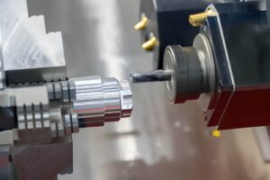
Flatness is applied to a surface when it needs to have even contact with another surface. This restricts the uplift and depression of the surface over a controlled area.
A size requirement can be met by a machined face, and it can remain in contact with the workpiece, but it may not all be even. One case in point is a sealing surface that is the proper thickness on a hydraulic block but is not flat, resulting in gaps around the gasket.
Here are the common causes of flatness variation in CNC machining:
- Stress release of material in the milling process.
- Thin sections under the cutting forces.
- Pressure of clamping during machining that is not uniform.
Typical surfaces that need flatness control:
- Hydraulic sealing faces.
- Fixture plates.
- Machine mounting surfaces.
Perpendicularity Control for Feature Alignment
When one feature needs to be square to another feature, then perpendicularity is used. It is frequently used on holes and bores that need to be aligned with a reference face that has been machined.
A hole drilled may be just the right size and be a bit off-center. The problem arises when the hole is intended for use as a bearing, pin, shaft, or alignment hole
For CNC parts, perpendicularity is important for:
- Parts of rotating shafts that fit into bearings.
- Holes for locating parts with dowel pins.
- Faces of a component that are machined to facilitate assembly.
The feature axis is aligned against the selected datum surface for verification during inspection.
Profile Tolerances for Complex Shapes
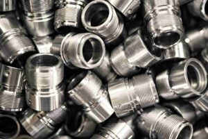
Profile tolerance is applied to surfaces that cannot be easily controlled by normal tolerances. It specifies the amount of deviation, or tolerance, from the CAD model that the actual surface can have.
A lot of CNC parts have curves, blended edges, and complex contours, and this tolerance is frequently seen in CNC milling. Inspection verifies the overall surface shape rather than many specific dimensions.
Typical uses include:
- Cavities of moulds & tooling surfaces.
- Spherical parts in the aerospace industry.
- Housed parts created from solid blocks.
The finished part is often compared with the original CAD geometry using CMM inspection and/or 3D scanning.
Runout Control for Precision Rotating Parts
Runout is used to apply to features that must remain parallel to a reference axis when they are rotating. It restricts the amount of rotation a surface of a shaft can make.
The correct diameter shaft could also cause vibration if the axis of the machine used to produce it is not controlled properly. This is why it is often necessary to specify a “runout” callout for bearing seats, journals, and rotating components.
Common applications include:
- Motor shafts.
- Bearing locations.
- Rotating tooling components.
| GD&T Tolerance | Controls | Common CNC Feature |
| Flatness | Variation across a machined surface | Sealing faces, mounting surfaces |
| Position | Location of a feature from datums | Bolt holes, dowel holes |
| Perpendicularity | Feature alignment at 90° | Bores, drilled holes |
| Profile | Complete shape of a surface | Moulds, complex milled parts |
| Runout | Movement during rotation | Shafts, bearing seats |
Common GD&T Mistakes in CNC Drawings
GD&T mistakes usually appear during the design stage, before machining starts. A drawing may include correct symbols and values, but the requirements can still be unclear if the datum system, tolerance selection, or feature relationships are not properly defined.
A good GD&T drawing explains how the part should be located, machined, and inspected. It focuses on functional requirements instead of controlling every possible variation.
Using Incorrect Datum References
Datums establish the reference system for machining and inspection. If the selected datum does not represent how the component is located in the assembly, the inspection results may not match the actual part requirement.
The primary datum should normally represent the main contact surface. Secondary and tertiary datums then control the remaining directions needed to locate the feature.
Before finalising the drawing, engineers should check:
- Does the primary datum represent the surface that supports the part?
- Will the machinist use the same reference during setup and inspection?
- Do the selected datums match how the component is assembled?
A correct datum structure reduces setup confusion and ensures the measured results reflect the intended function of the part.
Applying Tight Controls Without Functional Need
A common drawing issue is adding very strict tolerances to features that do not affect part performance. A smaller tolerance value does not automatically create a better component.
Tight controls require more accurate machining, additional inspection time, and sometimes special processes. They should be reserved for features that influence alignment, sealing, movement, or load transfer.
Before applying a strict GD&T requirement, consider:
- Will this feature affect assembly if it moves slightly?
- Does the part function require this level of control?
- Can the selected manufacturing process achieve and verify this tolerance?
Using practical tolerances keeps the drawing easier to manufacture without reducing the required part performance.
Confusing Size Tolerances With Geometric Controls
Size tolerance and geometric tolerance are used to solve different problems. Size tolerance, in addition to controlling the dimension of a feature, also controls the form of a feature; GD&T controls the location, orientation, or relationship of a feature.
The hole may be the correct size but be in the wrong location. The fastener might be inside the hole, but the whole assembly may be unsuccessful due to the hole pattern not aligning with the mating component.
Engineers should review:
- Is the need related to feature size or feature location?
- Is a position tolerance required as well as diameter control for the part?
- Does the controlled feature have a connection with another surface or feature?
These requirements can be separated, thus providing better drawings and not committing to erroneous inspection methods.
Missing Critical Feature Relationships
Some CNC parts rely on a relationship between features, instead of dimensions. A control-driven drawing may lack the interactive aspects required for the assembly.
For example, a bore in a bearing, a face on the mounting and locating holes could be the right size, but if they do not line up, the assembly will not function properly.
At drawing review:
- Does there need to be another feature that jogs into sync with this feature?
- Are holes, surfaces, or axes related to one another?
- Does the need to control this feature separately obscure a potential assembly problem?
For manufacturers, these relationships, when defined with the right GD&T controls, will help them understand the true intent of the design.
| Common Mistake | Manufacturing Impact | Better Approach |
| Missing datum reference | Creates unclear machining and inspection setup | Select datums based on assembly and functional surfaces |
| Over-controlled features | Increases machining effort and inspection requirements | Apply controls only to features affecting part function |
| Incorrect symbol use | Causes drawing interpretation problems | Use standard GD&T symbols and verify callouts |
| Missing feature relationships | Can cause assembly alignment problems | Control features based on their functional relationship |
GD&T Standards Used in CNC Machining
GD&T drawings follow recognised standards so engineers, machinists, and inspectors understand the same symbols and tolerance requirements. These standards define how geometric controls should be applied and interpreted during manufacturing and inspection.
ASME Y14.5 GD&T Standard
ASME Y14.5 is one of the most widely used standards for geometric dimensioning and tolerancing. It defines GD&T symbols, feature control frames, datum systems, and rules for applying geometric controls on engineering drawings.
- What does ASME Y14.5 define? It defines the meaning of GD&T symbols such as position, flatness, runout, and profile.
- Why is this standard used in CNC drawings? It provides a common method to communicate part requirements between design, machining, and quality teams.
- How does it help during inspection? It explains how features should be measured and how tolerance zones should be evaluated.
ISO GPS Standards for Geometric Tolerancing
ISO GPS (Geometrical Product Specification) standards provide an international system for defining part geometry and manufacturing requirements. They are commonly used in companies that follow ISO-based drawing practices.
- What do ISO GPS standards control? They define rules for size, form, orientation, location, and surface requirements.
- How are ISO GPS standards different from ASME Y14.5? Both systems use similar GD&T concepts, but symbols, rules, and interpretation methods can differ.
- Why should engineers specify the correct standard? It prevents confusion during production and ensures inspection follows the intended drawing requirements.

GD&T requirements should match the actual function of the part. Applying tight controls to every feature increases machining and inspection costs without necessarily improving performance. YD Rapid can review your drawings and manufacture CNC parts according to the specified datums, geometric tolerances, and inspection requirements.
FAQ’s
What does GD&T control in CNC machining?
GD&T controls the shape, position, orientation, and relationship of part features. It tells the manufacturer how accurately features such as holes, slots, surfaces, and shafts must be located and aligned. This helps ensure the finished part fits and works correctly during assembly.
What is the difference between tolerance and GD&T?
Dimensional tolerance controls the size variation of a feature, such as a hole diameter or part length. GD&T controls the functional relationship of features, such as the exact location of a hole pattern or the flatness of a mounting surface. Both work together on CNC drawings to define the required part condition.
Which GD&T symbols are most commonly used for CNC parts?
The most common GD&T controls used in CNC machining include position, flatness, perpendicularity, parallelism, profile, and runout. Position tolerance is widely used for controlling hole locations, while flatness and perpendicularity are often applied to machined surfaces that require accurate alignment.
Does GD&T increase CNC machining cost?
GD&T does not always increase machining cost. Cost increases when a drawing applies unnecessary tight controls that require extra machining time, special tooling, or advanced inspection. Proper GD&T reduces confusion and helps manufacturers apply controls only where the part function requires them.
What GD&T standard is used for engineering drawings?
The most commonly used GD&T standard is ASME Y14.5, which defines symbols, rules, and drawing interpretation methods. Many international companies also follow ISO GPS standards for geometric tolerancing.
GD&T Support for CNC Machining at YD Rapid
YD Rapid provides CNC machining support for parts that require GD&T-based manufacturing and inspection. Our engineering team reviews technical drawings before production to understand datum structures, tolerance requirements, and critical feature relationships.
We combine CNC machining capabilities with dimensional inspection to produce parts according to your drawing specifications. From prototype components to low-volume production parts, our team helps identify potential manufacturing issues early and provides practical feedback during the design review process.
Send your CAD files and drawings to YD Rapid for engineering evaluation, CNC machining support, and inspection-ready production solutions.