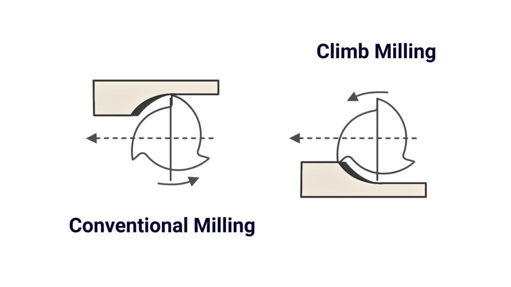
When comparing climb milling vs conventional milling, the main difference is how the cutting edge engages your workpiece. In climb milling, chips start thick and become thinner; in conventional milling, chips start thin and become thicker.
This guide explains how both methods work, their advantages and disadvantages, and their key differences. You’ll learn how to choose between them based on your CNC machine condition, material, workholding, and machining requirements.
What Is Climb Milling?
Climb milling, also called down milling or climb cutting, occurs when the cutting edge moves in the same direction as the workpiece feed at contact. In a typical peripheral cut, each tooth enters with a thick chip that becomes thinner toward exit.
The cutter tends to pull the workpiece or table into the cut. You need secure workholding and controlled backlash: mechanical clearance that allows movement before the feed drive takes up the load.
Advantages of Climb Milling
- Less entry rubbing: The tooth begins with substantial chip thickness, helping establish cutting rather than rubbing against the surface.
- Better finish potential: Stable engagement and effective chip evacuation often produce cleaner walls and profiles.
- Reduced wear: Less rubbing can limit friction and cutting-edge wear, depending on tooling, material, and cutting conditions.
- Broad CNC use: Suitable rigid machines can use climb milling for both roughing and finishing.
Disadvantages of Climb Milling
- Backlash-related pull-in: The cutter can draw the table through clearance, unexpectedly increasing engagement and risking tool or part damage.
- Setup sensitivity: Unsupported features, loose fixtures, and excessive tool overhang can allow deflection or vibration.
- Entry loading: Hard scale or uneven stock can impose heavy initial loads. Assess surface condition and entry strategy before cutting.
What Is Conventional Milling?
Conventional milling, also called up milling, occurs when cutting-edge motion opposes the workpiece feed at contact. Chip thickness starts near zero and increases toward exit in a typical peripheral cut.
Initially, the edge may rub or plough before a chip forms. The cutting force tends to oppose the feed, creating a different load direction that can be useful under specific CNC workholding and engagement conditions.
Advantages of Conventional Milling
- Alternative engagement behavior: Conventional milling opposes the feed and may suit specific force or engagement conditions. It should not substitute for correcting axis wear or instability.
- Useful with some scaled surfaces: Depending on engagement geometry, the tooth can enter beneath the hard outer layer and exit through it.
- Alternative force direction: It may improve stability where climb milling loads a poorly supported feature or fixture direction.
Disadvantages of Conventional Milling
- Entry friction: Thin initial engagement can generate rubbing and heat, especially with dull edges or insufficient chip thickness.
- Work hardening: Rubbing can harden susceptible materials such as stainless steel.
- Workholding demands: Some peripheral arrangements generate upward forces that clamps must resist.
- Chip recutting: Chips may return to the cutting zone, depending on cutter arrangement and evacuation.
Climb vs Conventional Milling: What Are the Differences?
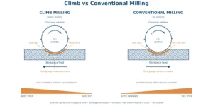
| Comparison | Climb Milling | Conventional Milling |
| Cutting direction | Follows workpiece feed at contact | Opposes workpiece feed at contact |
| Chip thickness | Thick to thin | Near zero to thick |
| Entry friction and heat | Less initial rubbing | Initial rubbing can add friction and heat |
| Forces and backlash | Pull-in risk with uncontrolled clearance | Opposes feed; lower pull-in tendency |
| Finish and wear | Often favorable with stable cutting | Rubbing and recutting may affect results |
| Application conditions | Rigid CNC setups; roughing and finishing | Specific support, surface, or engagement conditions |
Cutting Direction and Chip Formation
Clockwise spindle rotation alone does not identify milling direction. You must also locate the engagement side and the workpiece feed relative to the cutter. For the same spindle rotation, changing the engagement side changes the direction relationship.
Actual chip thickness depends on radial engagement and cutter geometry. The thick-to-thin description explains the cutting sequence; it does not mean every climb cut starts at the tool’s programmed feed per tooth.
For example, when you change from an outside contour to an inside pocket wall, keep track of which side contains uncut stock. A direction arrow without this context can be misleading.
Entry Friction and Heat
A real cutting edge has a finite radius. Below a sufficient chip thickness, it can push material aside instead of shearing it. Conventional milling encounters this condition at entry; climb milling generally establishes effective cutting sooner. Temperature still depends on speed, engagement, tool condition, and cooling.
Surface Finish, Tool Wear, and Cutting Forces
Table pull-in and workpiece deflection are different problems. Pull-in involves feed-system clearance; deflection depends on force direction and support. Neither milling method automatically prevents vibration or guarantees that forces hold the workpiece down.
Climb milling often produces a better surface finish and reduces tool wear by limiting entry rubbing. However, neither method guarantees a roughness value, tolerance, or percentage improvement. Evaluate the complete setup and inspect the result.
If you compare the two methods experimentally, keep the tool, material, engagement, and inspection method consistent. Record surface appearance, dimensional deviation, vibration, and edge wear rather than judging by sound alone. A smoother sounding cut does not necessarily mean the part meets its drawing requirements.
Conventional vs Climb Milling: How Do You Choose?
On a rigid CNC machine with controlled backlash, start by considering climb milling. Then check whether the stock, support, or toolpath requires a different approach.
CNC Machine Condition and Feed Control
On a well-maintained CNC machine with a rigid setup and properly controlled backlash, climb milling is generally the first choice. Before machining, check the feed system, spindle condition, and toolholding stability.
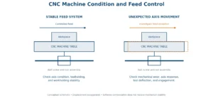
If you notice unexpected axis movement, chatter, or inconsistent dimensions, investigate mechanical wear, tool deflection, and cutting engagement. Switching to conventional milling should not replace correcting a machine or setup problem.
Material and Stock Surface
Clean, uniform stock provides more predictable engagement than castings or forgings with scale and uneven allowance. Climb milling commonly suits aluminum, steel, and stainless steel on stable setups; reduced entry rubbing is useful with work-hardening materials.
Where hard scale creates severe entry loading, evaluate conventional milling and an appropriate tool. Material hardness alone is not a reason to choose it. Use recommendations for the specific grade, hardness, and surface condition.
Workpiece Rigidity and Workholding
Identify unsupported walls and the directions in which the part can flex. Choose a cutting direction that loads the strongest available support. Conventional milling may help if climb milling loads a weak direction.
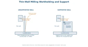
Improve support near the cut, shorten tool overhang, and adjust engagement before relying on a direction change. Neither method compensates for loose clamping or an unstable fixture.
Roughing, Finishing, and Toolpath Engagement
Do not assign conventional milling to all roughing and climb milling only to finishing. Climb milling can perform both on suitable CNC setups.
For roughing, prioritize controlled engagement and chip removal. For finishing, check deflection and dimensional consistency. Corners or uneven stock can increase engagement despite constant programmed feed. During full-width slotting, one side cuts in climb mode and the other in conventional mode; assess the actual contact rather than labeling the entire operation.
Common Milling Mistakes and How to Fix Them
Check the setup before reversing milling direction to address chatter, poor finish, or dimensional errors.
| Mistake | Possible Consequences | What to Check and Change |
| Ignoring backlash | Table pull-in and sudden overload | Inspect axis condition and the feed mechanism. Correct mechanical instability before machining. |
| Choosing direction only by roughing or finishing | Unnecessary rubbing or unfavorable forces | Evaluate machine condition, engagement, stock surface, and support. |
| Ignoring chip evacuation | Recut chips damage surfaces and edges | Check flute space, coolant or air delivery, and chip buildup. |
| Leaving thin walls unsupported | Deflection, taper, or chatter | Add nearby support, shorten overhang, and reduce engagement where needed. |
| Copying RPM without matching tool diameter | Unsuitable cutting speed and excessive wear | Calculate RPM from recommended cutting speed and diameter; match feed to tooling and engagement. See our CNC milling speed guide for RPM and feed calculations. |
| Ignoring corner engagement | Sudden overload or tool breakage | Review remaining stock in CAM; adjust entry, corner paths, or engagement. |
When diagnosing a problem, inspect the cutting edge and verify actual stock allowance before changing several settings together. Change one relevant variable at a time, document the result, and stop if movement or loading becomes unpredictable. This makes the cause easier to identify and avoids attributing every improvement to milling direction. For repeat production, confirm the chosen strategy on the first part, including wall dimensions and surface requirements, before applying it across the batch.
Keep these records with your setup notes so later operators can reproduce the verified conditions.
FAQs
Does Switching Between a Climb Cut and a Conventional Cut Require Spindle Reversal?
No. Switching between a climb cut and a conventional cut normally changes the feed path or engagement side, not the spindle rotation. Running a standard right-hand cutter backward does not convert climb milling into conventional milling.
Does the Same Contour Direction Work for Internal and External Profiles?
No. With fixed spindle rotation, internal pocket walls and external profiles require opposite contour travel directions to maintain climb milling. Identify the remaining material’s position relative to the tool instead of assuming clockwise travel always means climb milling.
How Can You Verify Milling Direction in CAM?
Check your CAM operation’s cutting-direction setting; labels vary by software. Simulate the toolpath with the stock visible, then confirm spindle rotation, feed travel, and engagement side. Inspect bidirectional passes and linking moves for unintended cutting in the opposite direction.
Conclusion
Choose milling direction according to machine condition, stock surface, support, and engagement. Climb milling is generally preferred on suitable rigid CNC setups, while conventional milling remains useful under specific conditions.
Send YD Rapid your drawings or CAD files, material, quantity, critical tolerances, and surface finish requirements. Our CNC milling team can review your part and recommend a suitable machining approach.