
CNC milling speed is usually discussed as spindle RPM. However, the useful value is the cutting speed at the tool edge. With carbide end mills, a practical starting range for 6061 aluminum is about 180 to 450 m/min. For mild steel, it is about 75 to 135 m/min, and for stainless steel, about 30 to 105 m/min. Actual values depend on the tool grade, cutter diameter, workholding, machine, and cutting operation, so the toolmaker’s data should be checked before production.
For instance, a 10mm carbide cutter operating at 300m/min will operate at approximately 9,550 RPM. The feed rate is approximately 2,290 mm/min for 3 flutes and a 0.08 mm/tooth chip load. The above RPM cannot be simply transferred to steel, since its proper cutting speed is much lower.
This article explains how to convert cutting speed into RPM and feed rate, then adjust the values for cutter diameter, flute count, chip load, radial engagement, axial depth, and tool reach. It also examines practical ways to increase cutting speed without causing chatter, excessive heat, poor surface finish, or unnecessary tool wear
How Do You Calculate CNC Milling Feed Rate?
Feed rate tells the machine how fast the cutter moves through the material. It is set by the spindle speed, number of cutting edges, and chip load per tooth.
Chip Load per Tooth
The amount of material removed from the workpiece by each flute during a revolution of the cutter is called chip load. It is normally given in mm/tooth.
The value is dependent on the material:
- Cutter Diameter
- Flute Geometry
- Tool Material
- Cutting operation
For instance, a 3-flute aluminum cutter may have a different chip load compared to a small 4-flute steel finishing cutter. Too little chip load can make the tool rub instead of cutting. Excessive force can cause excessive cutting force and overloading of the tool.
Feed Rate Formula
Use:
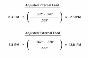
Feed Rate (mm/min) = RPM × Number of Flutes × Chip Load (mm/tooth)
If the spindle runs at 9,550 RPM, the cutter has 3 flutes, and the chip load is 0.08 mm/tooth:
9,550 × 3 × 0.08 = 2,292 mm/min
The programmed feed would therefore be about 2,290 mm/min.
Example: 3-Flute Carbide Cutter
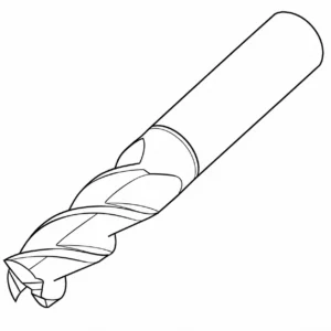
Suppose a 10 mm, 3-flute carbide end mill is cutting aluminum at 300 m/min.
First, calculate the spindle speed:
RPM = (300 × 1000) ÷ (π × 10) ≈ 9,550 RPM
Using a chip load of 0.08 mm/tooth:
Feed = 9,550 × 3 × 0.08 ≈ 2,290 mm/min
This gives a starting feed value. Before using it in production, check the cutter manufacturer’s recommended chip load and adjust for the radial engagement, axial depth, machine capability, and tool overhang.
What CNC Milling Speed Should You Use for Different Materials?
CNC milling speed should come from the tool manufacturer’s data for the actual cutter and material, then be adjusted for the cut being made. The figures below are useful reference points rather than universal settings.
Aluminum
In the case of aluminum, cutting speed may vary greatly depending on the cutter design and engagement.
According to Sandvik’s CoroMill Dura data, for one group of aluminium materials, the speed ranges from 100-130 m per minute, and for another group of aluminium materials, the speed is 680-950 m per minute, under the conditions mentioned. Also, changing the radial or axial engagement changes the recommended speed in the same table.
This is too general to say that “aluminum should always be milled at 300–450 m/min”. Use the value specified for the production job for the exact end mill, aluminum grade, radial engagement, and axial depth.
Mild Steel
The cutting speed for mild and low alloy steels is generally much lower than that of aluminum under the same conditions with a carbide milling cutter.
At one cutting condition and another engagement condition, Sandvik’s CoroMill Dura data indicates speeds of 145 m/min for unalloyed steel and 110 m/min at the other condition. The range of low-alloy steel is 80-175 m/min, varying with the material and the cut.
This is better than using one speed for all steels. Heavy radial cut and light adaptive style cut are not equal in terms of load on the cutter.
Stainless Steel
For stainless steel, the usable speed is dependent on the grade and cutting condition, requiring separate cutting data.
Sandvik specifies the values ranging from as low as 60 to 150 m/min for its ferritic/martensitic and austenitic stainless steel examples, with lower values at higher engagements. In the same data set, duplex stainless is marked with a speed of around 70 to 120 m/min.
It’s important to watch the actual cutting condition for stainless. Rubbing too much can cause the cutting edge to generate a lot of heat. Properly maintaining the cutter and keeping the chip thickness is more beneficial than raising the RPM.
Titanium and Nickel Alloys
The cutting speeds are much lower in these materials than in aluminum, due to the high thermal and mechanical load at the cutting edge.
According to Sandvik’s published data, the published data for an iron-based superalloy example indicates 25 to 40 m/min, and the nickel-based superalloys indicate 40–70 m/min for the CoroMill Dura data.
The data for titanium tools are also significantly different depending on the cutter geometry and operation. For instance, Harvey Tool has developed special variable-pitch end mills for titanium alloys, not just steel-cutting end mills.
With these materials, use the cutter manufacturer’s suggested Vc and chip load, then monitor spindle load, tool temperature, chip shape, and tool wear during the initial cut.
The important thing to note is that rather than choosing the cutting speed based on the material name, it should be based on the specific tool data. Within a material group, the difference between a light cut and a full-width cut can lead to a significant difference in the recommended Vc.
How Does Cutter Diameter Change Milling Speed?
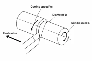
Spindle RPM is directly dependent on the cutter diameter for a given cutting speed. It is easier for a smaller cutter to spin at a high speed to maintain the same cutting speed as a larger cutter because there is less circumference to cover. If the radius of the cutter is increased, the distance it will cover per revolution will also increase, so the RPM of the machine will decrease.
The relationship is:
RPM = (Vc × 1000) ÷ (π × D)
Surface speed of cutting (Vc) in m/min and Cutter diameter (D) in mm.
Small-Diameter Cutters
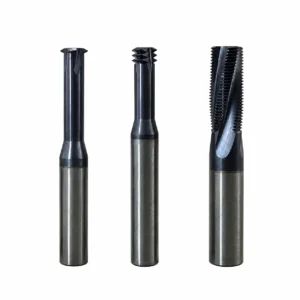
The spindle speed is increased for small cutters at the same cutting speed.
For instance, when using a cutting speed of 300 m/min, the 6 mm cutter needs:
RPM = (300 × 1000) ÷ (π × 6) ≈ 15,915 RPM
This may become a limitation of the machine. If the calculated RPM is over the spindle’s maximum allowable RPM, then use the spindle’s maximum RPM and calculate the spindle RPM based on the actual spindle RPM.
Large-Diameter Cutters
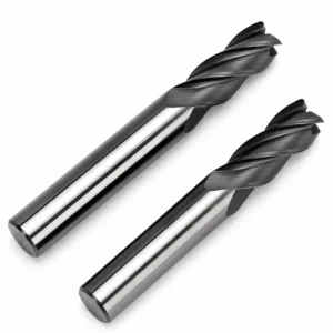
The larger the diameter of the cutter, the lower the RPM will be.
A 12 mm cutter, cutting speed of 300 m/min, requires:
RPM = (300 × 1000) ÷ (π × 12) ≈ 7,958 RPM
The RPM requirement is approximately half of the cutter’s since the diameter is twice that of a 6 mm tool.
This isn’t to say that the bigger cutter removes double the material. The cutting load is still a function of the radial engagement, axial depth, flute count, machine power, and tool geometry.
Practical RPM Example
Using 300 m/min for both tools:
| Cutter diameter | Required RPM |
| 6 mm | ≈ 15,915 RPM |
| 12 mm | ≈ 7,958 RPM |
- The important point is to calculate RPM from the actual cutter diameter, then check it against the machine limit.
- A 6 mm cutter may require a high-speed spindle to reach the recommended cutting speed, while a 12 mm cutter can reach the same Vc at a much lower RPM.
How Do Depth of Cut and Radial Engagement Affect Speed?
The cutter load changes with both axial depth and radial engagement. A 10 mm end mill taking a 1 mm side cut is not working under the same conditions as the same tool cutting a 10 mm-wide slot.
Axial Depth of Cut
Axial depth is the amount of cutter length working in the material. Use a 10 mm carbide end mill to machine 6061 aluminum. Each pass removes a small amount of the cutting edge (2 mm deep). With the same radial width, a 10 mm deep pass allows five times more cutting length to be engaged.
When spindle load increases over a deep pass, a cutback in the axial depth will lower the load without altering the cutter. The machine is also capable of clearing chips in between passes.
Radial Engagement
The width of the side entry of the cutter into the material. A radial engagement of 10% with a 10 mm cutter is approximately 1 mm. The cutter has only a light engagement, which means that less of its diameter is cutting at any given moment.
The 50% engagement represents that 50% of the cutter is in the material. The full-width slot has a width of 10 mm and creates a much heavier cut.
Full-Width vs. Light Engagement
A slotting is generally more difficult to make on the cutter than a light side cut. The tool features a wider contact area, a greater removal rate per revolution, and less chip clearance area.
If the manufacturer of the cutter has given data for a higher feed at 1 mm radial engagement, for instance, then this should be taken as a guide and not just applied to 10 mm of slot. A cutting data set is needed for slotting.
One of the more practical approaches to increase material removal is to decrease the radial engagement and perform multiple passes, instead of attempting to make the cut in one pass. Final values are still dependent on the cutter diameter, the number of flutes, material, axial depth, machine power, and tool overhang.
How Can You Increase CNC Milling Speed Without Losing Quality?
An increase in production does not always increase RPM. The superior outcome in many jobs is achieved by the combination of keeping a useful chip load, minimizing the engagement of the cutter, and keeping the chips away from the cutting edge. Change one thing at a time to see how it affects the cut.
Increase Feed Before Simply Increasing RPM
Higher feed rates correspond to higher chip loads:
The feed rate is calculated as:
RPM x number of flutes x chip load.
For instance, with a 0.05 mm/tooth chip load, 4 flutes at 8,000 RPM:
8,000 × 4 × 0.05 = 1,600 mm/min
At the same spindle speed, the feed is reduced by 2,240 mm/min when a chip load of 0.07 mm/tooth is applied to the cutter and material.
This boosts feed without increasing spindle speed. The upper limit was still set by the machine load and the range of the chip load of the cutter manufacturer.
Reduce Cutter Engagement
The material width to be cut down does not need to be wide for each pass with a cutter. Less radial engagement will reduce the cutting force and provide more clearance for chips to exit the cut area.
A 10% radial cut for a 12 mm end mill is a 1.2 mm cut. The same tool with a 6 mm wide slot makes 50% engagement and exerts a significantly greater load on the cutter.
But a constant-engagement path keeps the cutter from plunging into a lot of material at corners when used for roughing pockets. This is frequently a more effective method of increasing feed throughout the toolpath.
Use the Right Tool for the Cut
The selection of tools should be appropriate for the operation. A small cutter is good for small features, but it can cause excessive cycle times for large amounts of stock removal.
As an example, a large pocket cut with a 6 mm cutter may need to be cut many times. If the machine, pocket geometry, and toolpath permit, more material can be removed per pass using a 12 mm or 16 mm cutter.
The feed calculation is also influenced by the flute count. The more flutes, the greater the feed at a given chip load, but there must be sufficient flute space for the chips generated by the cut.
Improve Chip Evacuation
Re-cutting chips is a waste of cutting power and may cause surface damage. This is evident in deep pockets, narrow slots, and holes drilled.
Apply air blast, coolant, and through-tool coolant, as required for the material and cutter combination. Do not make the pocket too tight to allow chips to slip through where the design allows.
RPM is not usually the first correction when there is a buildup of chips at the bottom of a pocket. Always check the direction of the coolant, air pressure, toolpath direction, flute space, and cutting depth first.
What Causes Chatter at Higher Milling Speeds?
Chatter is a vibration between the cutter, machine, workpiece, and toolpath. It often appears as regular marks on the machined wall, a harsh cutting sound, or a changing spindle load. Increasing speed can expose an unstable setup, but the spindle speed is only one part of the problem.
Tool Overhang
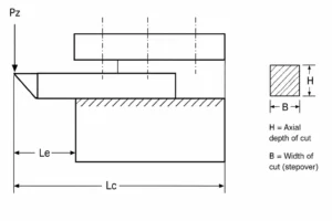
The farther the cutter is from the cutter holder, the more deflection will be possible. This is more evident when using small-diameter cutters and deep features.
Minimize the tool projection to the feature. For a deep pocket, a shorter, more controlled cutter may provide a cleaner wall than a long-reach cutter for the entire depth in one cut.
Workholding and Machine Rigidity
Even with a suitable cutter, a part can vibrate if it is movable in the workholding. Part examples are thin plates, narrow sections, and parts clamped far from the cut area.
Where feasible, support work near the cutting area. If the plate is thin, the addition of a backing support may have a dramatic effect on the result, as the cutter is not pushing the plate away during the cut.
Spindle Speed and Harmonics
The natural vibration frequencies of the cutter and machine can cause chatter at some spindle speeds, but not at others.
If there is a regular pattern, attempt to make a small change in RPM instead of a big change. For instance, it is sometimes possible to shift the cutting frequency to a more stable range by increasing the RPM from 8,000 to 8,500. Do not use the wrong feed for the new RPM, or the chip load may be changed unintentionally.
Cutter Engagement
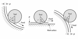
The amount of cutting force applied to the tool and workpiece increases with the size of the engagement. If the part geometry is not changed, then the force may be decreased by decreasing the radial width of cut.
If a cutter chatters during heavy side-cutting, then try to decrease the radial engagement first. A deep pass might also be useful if the problem persists; the lower the axial depth, the better. This is typically more helpful than just cranking the spindle up to see if the vibration goes away.
How Do Tool Condition and Tool Geometry Affect Milling Speed?
Some of the practical limits are determined by the cutter itself. Two end mills cut with the same diameter may have different edge conditions, flutes, carbide grade, and cutting geometry, and so perform differently. A worn tool can also convert a good cutting speed into a bad cut.
Sharp vs. Worn Cutting Edges
Sharp edge cuts through the material cleanly. As the edge gets worn, more of the edge will come into contact with the workpiece. The lower the cutting temperature, the more inconsistent the chips will be, and the surface of the workpiece may have a mark or burr.
In such cases, for instance, where a normal cutter began to give a rough strip in the feed direction, examine the cutting edge rather than changing the programmed speed. This can also be caused by a chipped edge, even if the tool has only made a few parts.
Flute Count
The feeding rate and chip space will be affected by flutes. A 2-flute cutter feeds at 800 mm/min with the same 8, 000 RPM and the same 0.05 mm/tooth size. A 4-flute cutter feeds at 1,600 mm/min, while the same 0.05 mm/tooth and 8, 000 RPM are used with the 2-flute cutter.
The 2-flute tool is designed to clear large chips from the cut with more clearance between the flutes. A higher flute cutter can achieve a higher feed with the same chip load, but the smaller flute space may be a problem when the chips generated by the cut are large.
Carbide Grade and Cutter Geometry
The cutter must be the same type of material and the same type of cut. Aluminum is typically allowed sharp edges and geometry that move chips away rapidly. Just because a cutter is carbide doesn’t mean it is good for aluminum.
Geometry also affects the approach to and departure from the material of the cutter. Different helix angles affect the cutting action and chip evacuation, and variable-pitch cutters can help reduce vibration.
How Should CNC Milling Speed Change Between Roughing and Finishing?
Roughing and finishing have different jobs. Roughing removes most of the stock. Finishing removes the small amount left on the surface and establishes the final size. Using the same cutting conditions for both operations can waste tool life and give a poor finish.
Roughing
Roughing shall not overload the cutter. Maintain an adequate clearance to allow chips to escape the cut and keep cutter engagement under control.
Multiple axial passes may be better than trying to get the cutter to full depth in a single pass for a deep pocket.
In the cutting process, pay attention to the load of the spindle and the discharge of chips. When approaching the power limit, it may be more helpful to decrease radial engagement rather than feed.
Semi-Finishing
When heavy roughing, leave enough stock for the final cut rather than removing the cut size. For instance, if a pocket wall is required to finish at 50.00 mm, then the wall should be rough cut to approximately 49.7 to 49.8 mm, and the remainder of the stock should be roughed out and cut out for semi-finishing and finishing. The actual allowance is dependent on the cutter, size of part, material, and finish required. This will eliminate the burr created from roughing before the final pass.
Finishing
Finishing is best performed at a low and steady pace. Areas with a higher density of cuts should not be entered into suddenly by the cutter, or if the toolpath is irregular, it should not change load.
Finishing cutters should be used, and finishing should be done under controlled conditions. One finishing pass is usually better than multiple finishing passes for a critical wall due to the smoother load on the cutter.
CNC Milling Speed Problems and Practical Fixes
Most milling problems give a useful clue before the part fails. Heat, burrs, chatter, poor finish, and tool wear can point to a cutting-condition problem. Check the symptom first, then change the setting most closely related to it.
| Problem | Check first | Practical fix |
| Cutter gets hot | Speed and chip load | Lower speed and check chip load |
| Aluminum sticks to the cutter | Tool edge and chip removal | Use a sharp aluminum cutter and improve chip evacuation |
| Chatter marks | Tool overhang and engagement | Shorten the tool and reduce engagement |
| Poor surface finish | Tool wear and vibration | Change the cutter and check tool support |
| Fast tool wear | Cutting speed and heat | Reduce the cutting condition and check the coolant |
| Cutter breaks | Feed, depth, and tool reach | Reduce cutting load and shorten tool reach |
| Large burrs | Tool edge and finishing pass | Replace the worn tool and clean up the final pass |
CNC Milling Speed: Practical Starting Point
Start with the material and cutter, not with an RPM number. Check the tool manufacturer’s cutting data for the material being machined, then calculate the spindle speed from the cutter diameter.
The working sequence is:
Material → cutter → cutting speed → RPM → chip load → feed → depth and engagement → machine check → test cut
For example, if the selected cutting speed is 300 m/min and the cutter diameter is 10 mm:
RPM = (300 × 1000) ÷ (π × 10) ≈ 9,550 RPM
If the cutter has 3 flutes and the chip load is 0.08 mm/tooth:
Feed = 9,550 × 3 × 0.08 ≈ 2,290 mm/min
Before running the full job, check that the calculated RPM and feed are within the machine’s spindle and feed limits. Also check the cutter’s recommended axial depth and radial engagement. A test cut can then show whether the selected values suit the actual setup.
Published cutting data should be treated as the starting condition. During production, use the cutting result to make controlled adjustments. Check tool wear, spindle load, chip formation, surface finish, and part geometry before increasing speed. A higher RPM is useful only if the cutter and machine can handle the resulting cutting load.
CNC Milling Speed FAQs
What Is CNC Milling Speed?
CNC milling speed refers to the cutting speed at the tool edge, normally given in m/min. It is different from spindle speed, which is measured in RPM.
How Do You Calculate CNC Milling Speed?
Use the cutter diameter and spindle speed:
Vc = (π × D × RPM) ÷ 1000
For a 10 mm cutter running at 9,550 RPM, the cutting speed is about 300 m/min.
What RPM Should I Use for CNC Milling?
Calculate RPM from the recommended cutting speed for the material and cutter. For example, a 10 mm cutter at 300 m/min requires about 9,550 RPM. Check the machine’s maximum spindle speed before programming it.
How Do You Calculate CNC Milling Feed Rate?
Use:
Feed = RPM × Flutes × Chip Load
At 9,550 RPM, with 3 flutes and 0.08 mm/tooth chip load:
9,550 × 3 × 0.08 ≈ 2,290 mm/min
What Is a Good Milling Speed for Aluminum?
Value varies according to the grade of aluminum and the cutter. The 300 m/min corresponds to approximately 9550 RPM for a 10 mm carbide cutter. Take the cutting information provided by the cutter manufacturer as the basis.
Should CNC Milling Speed Change for Different Materials?
The cutting speed should vary according to the material. It is possible to achieve a much higher cutting speed with an aluminum cutting speed than with a stainless steel cutting speed when using the same cutter. Look at the data from the toolmaker for the material group.
What Happens If the Milling Speed Is Too High?
The cutting edge can be very hot and deteriorate faster. Built-up material, poor surface finish, discoloration, and/or premature tool failure may also occur.
What Happens If the Milling Speed Is Too Low?
The cutter may rub rather than form a good chip. This can result in heat, poor finish, burrs, and buildup of material, especially with aluminum.
How Does Cutter Diameter Affect Milling Speed?
A larger cutter needs a lower RPM for the same cutting speed. At 300 m/min, a 6 mm cutter needs about 15,915 RPM, while a 12 mm cutter needs about 7,958 RPM.
Should Milling Speed Be Reduced for Deep Cuts?
Deep cuts can increase tool engagement, cutting load, and heat. Check the tool manufacturer’s data for the specified depth and engagement. If spindle load or vibration rises, reducing axial depth or radial engagement can be more effective than changing RPM alone.
Need a CNC milling quote with suitable speed and feed settings? Send YD Rapid your CAD model, material grade, drawing, quantity, cutter details, tolerances, and surface-finish requirements. We can review the part and machining conditions and prepare a quote based on the actual job.