Key Takeaways
- Polycarbonate should be machined with a sharp cutting edge because a dull tool creates more rubbing at the cut. This raises heat and can leave melted edges, burrs, and surface marks.
- Cutter geometry affects chip removal. A cutter with sufficient flute clearance gives chips enough room to leave the cutting zone rather than being trapped and cut again.
- Cutting speed and feed should be selected together with the cutter diameter and flute count. A high spindle speed with a low feed can generate excessive heat because the tool spends more time rubbing the material.
- Deep pockets need good chip evacuation. Chips left at the bottom of a pocket can be recut by the cutter, raising the temperature and leaving marks on the finished surface.
- Drilling requires extra care because the hole gives chips less space to escape. For deeper holes, controlled pecking and chip removal can prevent the drill from cutting through packed chips.
- Thin polycarbonate sections can move under cutting pressure. Supporting the part near the cutting area reduces movement and prevents the cutter from pushing the material off the intended path.
- Cracks can start around drilled holes, sharp internal corners, and thin sections. These areas should be checked after machining, especially if the part has already been formed or stressed before CNC work.
- Internal radii should be large enough for the selected cutter. A very small radius forces the use of a smaller tool, which can increase cutting passes and make heat control more difficult.
Introduction
Polycarbonate is easier to cut than many engineering materials. However, obtaining a clean machined part requires control over heat, chips, and cutting pressure. A sharp cutter can produce a clean edge, while excessive heat can soften the material and leave melted areas, burrs, or marks on the surface.
The problem becomes more noticeable in deep pockets, drilled holes, thin walls, and small internal features. Chips can remain inside these areas and pass through the cutter again, which adds heat and can damage the finished surface. A tool that is suitable for an open milling cut may therefore need different cutting conditions for a deeper feature.
Cracking also needs attention during machining. Small cracks can develop around holes, sharp corners, and thin sections if the cutting force is too high or the material is not properly supported. Existing stress in the polycarbonate can make these areas more sensitive to machining.
For this reason, polycarbonate CNC machining starts with the cutter and the part geometry, then moves to the cutting parameters. The sections below cover tooling, cutting speeds and feeds, chip evacuation, drilling, and the machining practices used to reduce surface damage and cracking.
What Makes Polycarbonate Different to Machine?
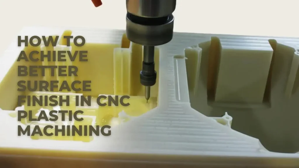
Compared with many other engineering plastics, polycarbonate is sensitive to heat and cutting pressure. Proper plastic CNC machining methods help control melting, cracking, and dimensional distortion.
Polycarbonate can soften from cutting heat, and its chips can remain around the cutter during machining. Thin sections can also move under cutting pressure. These three points affect tool selection, cutting conditions, and workholding.
Heat Buildup During Cutting
Polycarbonate can become soft at the cutting edge if exposed to excessive heat. A dull tool will generate more friction, and any chips trapped inside will add heat as well. This may lead to melting edges, burrs, or marks on the surface after the machining operation. Using a sharp cutter and managing the chips keeps the cut cooler.
Chip Formation and Evacuation
With the milling of polycarbonate, long chips can be formed. These chips should only remain in the cutting area and should not be left in the pocket. When the cutter retrieves them again, the chips are recut, and an increase in heat is created. Air blast is used to remove chips from pockets and to open up milling areas.
Cutting Pressure on Thin Sections
When the cutting tool penetrates the material, the thin wall will deflect. This may cause the wall to become misaligned or alter the final dimensions of the wall. Hold the piece near the cutting area and do not allow too much engagement by the cutter on thin pieces.
CNC Tooling for Polycarbonate
A sharp edge that removes an appropriate chip is best for cutting polycarbonate. The volume of flute space must also be equal to the material to be removed. Make the cutter as short as possible for deep features, depending on the geometry.
Single-Flute End Mills
Cutting with a single flute cutter provides a large chip space to each flute. Good for slots and pockets, as polycarbonate chips will not pack tightly between the flutes and will be removed from the cutting area.
Chips can be channeled up in a 35° to 45° helix for milling. A positive rake and sharp edge decrease the cutting force on the workpiece.
Two-Flute Carbide Cutters
Two-flute cutters offer another cutting edge, but they still have more chip space than three- or four-flute cutters. They can be used for profiling, pocket walls, and finishing cuts for polycarbonate.
For general plastic machining, a 30°to 40° helix angle provides a good starting point. Do not dull the edge, as it causes more rubbing and heat.
Polished Cutting Edges

A clean flute facilitates chips to run more smoothly out of the cutter. It also minimizes the adhesion of the polycarbonate layer to the flute while cutting.
The cutting edge should be sharp. When the edge is worn, the cutter begins rubbing more against the material and will cause a cloudy or melted spot on clear polycarbonate.
Tool Diameter and Overhang
The largest cutter that will fit into the feature should be used. An increase in diameter provides increased stiffness of the tool, but too much stick out will make the cutter deflect easily.
A 6 mm cutter with 30 mm stick out is much less rigid than a 6 mm cutter with 10 mm stick out, for instance. Do not let the exposed part be long, particularly in thin walls and deep pockets.
Drill Selection for Polycarbonate
The drill must have sufficient flute space to remove chips from the hole. Clear flutes help prevent chips from getting trapped in the hole, and a sharp point means that less force is needed to get into the material.
To remove chips from the flutes, use peck cycles for deeper holes. A 135° split-point drill helps to reduce walking at entry and can be used to help maintain the hole position.
Tool Selection Table
| Tool | Cutting Geometry | Typical Use | Practical Selection Point |
| Single-flute end mill | 35°–45° helix, positive rake, one large flute | Slots, pockets, contouring | Use when chip space is the main concern |
| Two-flute carbide end mill | 30°–40° helix, positive rake, two cutting edges | Profiling, pocket walls, finishing | Gives more cutting edges while retaining chip space |
| Polished end mill | Polished flutes, sharp cutting edge | General milling, clear polycarbonate | Reduces chip adhesion and rubbing |
| Large-diameter end mill | Larger core and higher bending stiffness | Open pockets, roughing, profiles | Use the largest diameter that fits the feature |
| Short-stick-out cutter | Same cutting geometry with reduced extension | Thin walls, deep pockets | Keep exposed length as short as the feature permits |
| Carbide drill | Sharp point, open flutes | Through holes, blind holes | Select flute length and drill diameter for hole depth |
| 135° split-point drill | Split point, sharp lips | Hole starting and drilling | Reduces walking at entry |
Cutting Parameters for CNC Machining Polycarbonate
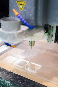
Polycarbonate does not give much warning before heat starts affecting the cut. A useful starting point is to watch the chips and the machined edge. If the chips are leaving the cutter cleanly and the edge stays sharp and dry, the cutting conditions are closer to the right range. If the material starts sticking to the flute, the settings need attention.
Spindle Speed
Use the surface speed recommended by the cutter manufacturer, and calculate the RPM for the diameter of the cutter to be used. Under the same cutting conditions, a small cutter may need more RPM than a larger cutter.
If the RPM is selected too high for the feed rate, then the cutting edge will rub against the polycarbonate and can create heat. Helpful indications that the settings need to be adjusted are melted edges, material sticking to the flute, and a softened surface.
Feed Rate
The feed rate should allow the flute to have sufficient material to make a good chip. Excessive feeding can result in thin sections being pushed out of place and a rough edge, and a very low feed can lead to rubbing and heat.
For milling:
Feed rate = RPM x number of flutes x chip load
For instance, a two-flute cutter, with a chip load of 0.05 mm/tooth, and running at 12,000 RPM will yield a feed rate of 1,200 mm/min.
Depth of Cut
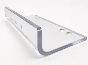
Heavy cuts should be used for well-supported areas where there is ample room to chip. Narrow features and thin walls should be cut with less engagement than others because it will not allow the cutter to push the material away.
When finishing, leave a little bit of the stock. This allows the finishing cutter to remove a controlled amount of material and removes the need for a heavy roughing cut to make the final wall.
Step-Over for Pocket Milling
The larger step-over will remove more material in each pass and will impose a heavier load on the cutter. This can be apparent during thin-wall pocket machining.
With a thin wall, decrease the step-over to help lower cutter pressure. In a relatively open pocket with good support, a larger step-over may be applied in the roughing operation, and then a smaller finishing step-over may be applied.
How to Prevent Cracking During Polycarbonate Machining
Cracks usually start at places that see more cutting force or heat than the surrounding material. Holes, thin walls, sharp internal corners, and previously formed sections need closer attention during machining.
Reduce Cutting Pressure
Always use a sharp cutter and don’t make a deep cut in a single pass. An over-stick-out tool can also cause the tool to bounce back and impact the part. A smaller radial engagement and a controlled finishing pass can help to minimize the force on the material for thin features.
Support Thin Walls
As the cutter cuts into the material, a thin wall can move. It is possible for the upper part of a piece of work being held to move away from the cutter if the workholding is only supporting the base. Support in as near to the feature as possible, but with adequate clearance for the tool and chips.
Avoid Sharp Internal Corners
A perfectly sharp inside corner cannot be made with a milling cutter. The radius required should be appropriate for the type of cutter to be used. The shallow corner radius will require a small cutter, which will create larger tool pressures and may be more difficult to remove heat from the tool. The larger the radius, the more room the cutter has for a clean cut.
Control Heat Around Holes
Drilling can focus heat around the hole because chips are restricted from getting away from the hole. This can be minimized with a sharp drill, proper feed, and good flute path. If a hole is deeper, remove the drill frequently to remove chips and not to let them accumulate in the hole.
Consider Existing Material Stress
Formed, bent, cut from sheet, and previously heated polycarbonate can have internal stress. Stressed areas may be revealed and initiate cracks when the material is removed from a stressed area, or when a hole is created in the stressed area. Before heavy cuts are made, examine the area around the proposed machined features for any previous forming operations, if one was performed.
Milling Polycarbonate Without Melting the Material
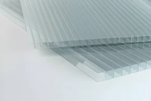
A melted edge usually means the cutting zone is getting too hot. Start with the cutter condition, chip load, and amount of material engaged in the cut before changing coolant. The goal is to keep the tool cutting cleanly and move the chips away from the part.
Keep the Cutting Edge Sharp
A worn edge causes more rubbing against the workpiece. This can create hot spots and may cause a smeared edge on polycarbonate. Always use a sharp cutter and examine the edge if the surface begins changing during a job.
Maintain Proper Chip Thickness
The cutter should break off a small, measurable chunk of material and not skim by it with negligible material removal. If the feed is too low for the chosen RPM, it can result in rubbing and heat. Start with the recommended chip load of the cutter manufacturer, and modify for the actual cutter engagement.
Clear Chips From Deep Pockets
Chips may become stuck in deep pockets under the cutter. These chips can be hand picked up, recut into chips again, and heat at the cutting edge will increase. Provide adequate flute clearance; clear the pocket with air when cutting to ensure the cutter is fed clean material.
Use Air Blast for Chip Removal
An air blast can blow away chips from a cutting piece without adding fluid to the piece being cut. In deep features, where chips may pool, blow the air in the direction of the cutting area and not directly down into the pocket.
Avoid Excessive Tool Engagement
If the step over is large or the radial engagement is deep, more polycarbonate will be removed with every pass. This increases the cutting pressure and heat. Decrease the engagement when the cutter begins to leave melted edges or excessive burrs or marks on the surface.
Drilling Polycarbonate CNC Parts
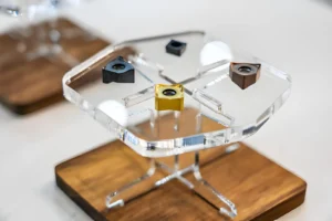
Drilling needs more control than a simple plunge into the material. The hole gives chips little room to escape, so drill geometry, feed, hole depth, and chip removal all affect the edge of the hole and the surrounding material.
Drill Geometry
Drill with sharp flutes for easy removal of chips from the hole. To facilitate a clean start for the drill and minimize walking on top of the surface, a 135° split point is used. The cutting edge should be kept sharp; otherwise, the rubbing and heat around the hole will increase due to the wear of the drill.
Shallow vs Deep Holes
The shorter the chip path out of the hole, the easier the shallow hole is to machine. When removing chips in deep holes, care must be taken to remove the chips, since chips will pack and cause heat and damage to the hole wall.
When drilling a deep hole, do not drive the drill through the packed chips. Remove the drill now and again to clear the flutes.
Peck Drilling
In a peck drilling operation, the drill has an opportunity to clear chips from the hole. The peck depth should be appropriate to the hole depth and drill diameter and not necessarily the same for all holes.
A shorter peck can be used to avoid chip packing in deeper holes. The drill should come back sufficiently far from the hole to free up the chips before it reenters the hole.
Stopping Burrs around Hole
Burrs may form when the drill is removed from the material, especially when the edge of the drill has worn or if the feed rate is too high at the end of drilling. Use of support behind the workpiece will help to minimize breakout at the exit. The remaining edge can then be removed by a light chamfer or deburring operation, which doesn’t apply much pressure to the polycarbonate.
Preventing Cracks at Hole Edges
Cracks may begin at the edge of the hole if the heat or cutting pressure generated by the drilling operation is too great. Always maintain a sharp-edged drill, clear the chips, and don’t push the tool too far into the material. Holes that are located close to an edge may require additional attention as there is less material surrounding the hole to provide support to the cutting force.
CNC Milling vs CNC Turning for Polycarbonate
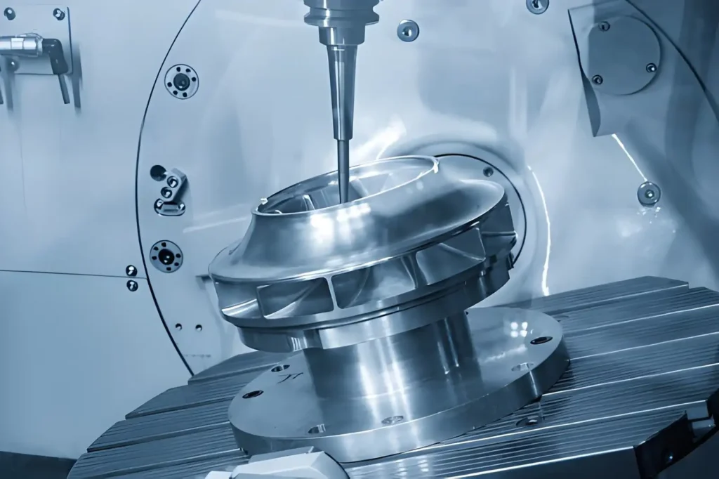
CNC milling is suitable for polycarbonate parts with flat surfaces, pockets, slots, drilled holes, and complex profiles.
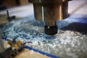
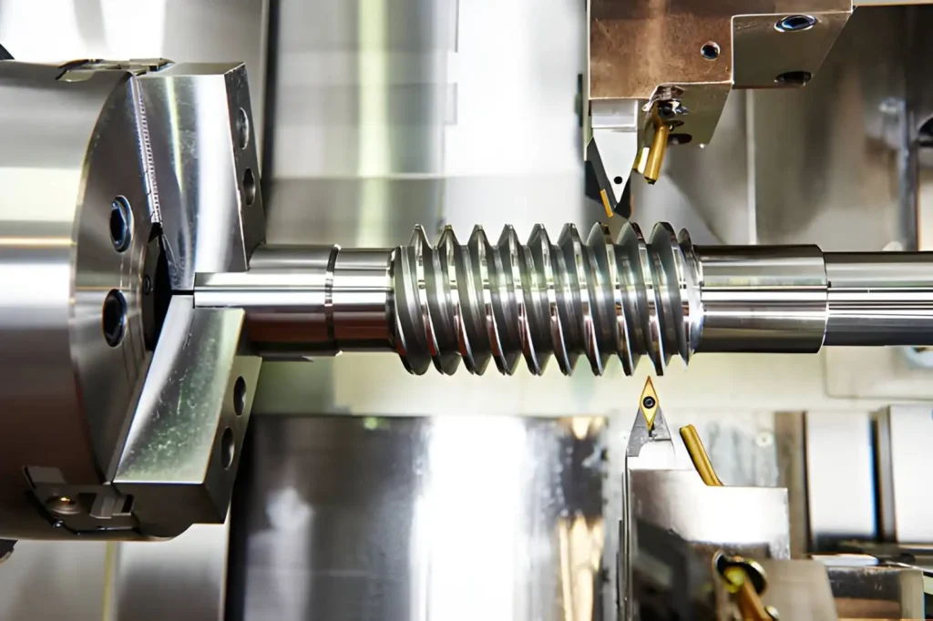
The main difference is the kinematics of the cutting process. In milling, the workpiece is fixed while a rotating multi-point cutter removes material along programmed axes. In turning, the workpiece rotates about the spindle axis while a stationary cutting tool removes material from the rotating surface.
| Technical Feature | CNC Milling | CNC Turning |
| Primary motion | Rotating cutter with linear axis movement | Rotating workpiece with linear tool movement |
| Main geometry | Prismatic, stepped, contoured, and irregular | Cylindrical and rotational |
| Typical features | Pockets, slots, holes, flats, steps, contours | OD, ID, faces, grooves, chamfers, shoulders |
| Cutting tools | End mills, drills, reamers, face mills | Turning inserts, boring bars, grooving tools, drills |
| Cutting engagement | Radial and axial engagement changes with toolpath | Tool engages the rotating OD, ID, or face |
| Workholding | Vise, fixture, soft jaws, vacuum fixture | Chuck, collet, soft jaws |
| Axis reference | Features can be machined from several tool directions | Features are primarily generated around the spindle centerline |
| Typical polycarbonate parts | Housings, covers, plates, brackets | Bushings, sleeves, spacers, rollers |
| Secondary features | Multi-face machining is possible with suitable setups | Flats, slots, and cross-holes may require milling |
| Main process consideration | Cutter engagement, chip evacuation, and wall deflection | Workpiece support, tool engagement, and chip control |
Polycarbonate Part Design for CNC Machining
A polycarbonate drawing can make machining unnecessarily difficult even if the finished part looks simple. Before releasing the drawing, check the wall sections, pocket proportions, hole locations, cutter access, and corner geometry. These features determine what tooling can reach the part and how much support remains during machining.
Wall Thickness
Avoid reducing the wall thickness from a function just to save material. A thin section will present less material to be held up by the cutter and provide less room for workholding. Where a very thin wall is required, it is best to avoid having several machined features back to back, as the remaining material may not be easy to hold in the machine.
Internal Corner Radii
Choose the internal radius for the desired cutter. A 6 mm cutter, for example, will have a minimum internal radius of approximately 3 mm, which means that the radius can be used to get a bigger cutter in the corner and potentially eliminate the need for a small tool operation.
Pocket Depth
Consider the depth-to-width ratio instead of just the depth. A narrow pocket, 40 mm deep, may need a long cutter, while a 40 mm deep pocket, very wide, can be cut with a shorter, stiffer cutter. Sometimes the actual depth is not important for function and could be reduced to make the machining easier.
Hole Location
Ensure that there are adequate margins around holes and other features. If a hole is located close to an edge, you may have a thin web that requires extra support while being machined. If only a small gap exists between the holes, they can also cause this.
Tool Access
Check the complete tool path, not just whether the cutter diameter fits the feature. The holder must also be cleared of adjacent walls. Although a wide pocket may be suitable for a standard tool, if there is a narrow opening above that deep pocket, then a long tool may be needed.
Non-Functional Sharp Features
It is not easy to create just small slots, sharp internal corners, or tiny recesses, so don’t simply add them because they are easy to create in CAD. If the feature serves no function in the assembly, clearance, sealing, or function, the supplier may be able to use a larger cutter and fewer machining operations to remove the feature.
Coolant and Chip Removal in Polycarbonate Machining
Polycarbonate does not always need flood coolant. The main concern is keeping chips away from the cutter and preventing heat from building at the cutting edge.
Air Blast
Use air blast to remove chips from the cutting area. Point the air at the toolpath, rather than at a pocket, to remove chips.
Flood Coolant
Flood coolant can be used when the machining setup and material allow it, but it should not replace proper chip removal. Before production, determine the grade of polycarbonate and the compatibility of coolant.
Dry Machining
For many milling operations, dry machining can be applied if the sharpness of the cutter is retained and the chips are removed from the cutting area rapidly. Be alert for signs of melted edges, material sticking to the tool, and surface marks.
Chip Evacuation in Deep Features
Chips may get stuck in deep pockets or narrow slots. Ensure flute space, air blast, and appropriate step down to prevent chips from lying in the flute and re-entering the cutter.
CNC Machining Service for Polycarbonate
Polycarbonate parts often need a review before machining, especially when the drawing includes thin walls, deep pockets, small holes, or clear surfaces. At YD Rapid, our engineering team reviews the part geometry, material condition, and machining approach before production starts. This early review helps identify tool access, workholding, and feature issues while the drawing can still be adjusted.
As an ISO-certified manufacturer, YD Rapid provides CNC milling and CNC turning for polycarbonate parts from prototype to production. Our engineers also provide free DFM feedback based on the submitted drawing, then prepare a fast quotation using the material and project requirements.

Send your CAD file, drawing, and polycarbonate grade to our engineering team for review before machining begins.
FAQs
Can polycarbonate be CNC machined without coolant?
Many polycarbonate milling jobs can run dry with a sharp cutter and good chip removal. Air blast is often enough to keep the cutting area clear. Flood coolant can also be used based on the material grade, machining operation, and shop setup.
What causes white marks on CNC machined polycarbonate?
White marks can come from local stress, cutter rubbing, excessive pressure, and heat. So, always check the machined edge and the workholding first.
Can polycarbonate (PC) be machined with standard carbide end mills?
Yes, polycarbonate can be cut using a standard carbide end mill. However, if the flute geometry is not appropriate for the tool and the edge is worn, there will be more heat and rubbing at the cut.
Why does polycarbonate melt during CNC milling?
Excessive heat may occur because the tool rubs, chips are not removed from the cut, or tool engagement is excessive. Before changing spindle speeds, check the chip load, condition of cutters, radial engagement, and chip evacuation.
How should deep holes be drilled in polycarbonate?
Regulations for clearing chips from deep holes. Sharpened drills with open flutes are useful to remove chips from the hole, and peck drilling can keep chips out of the hole. The length of the peck needs to be matched to the diameter of the hole and depth.
Can stressed polycarbonate crack after machining?
Previously formed, bent, and heated polycarbonate can contain internal stress. Machining a hole, slot, and sharp corner can release that stress locally and start a crack. This is worth checking before machining formed sheet and molded sections.
How much material should be left for a finishing pass?
Leave enough stock for the finishing cutter to remove a clean, controlled layer. The amount depends on the cutter size, roughing method, wall thickness, and feature geometry. A heavy finishing allowance can create unnecessary cutter pressure on thin polycarbonate walls.
Does polycarbonate require a different feed rate for small cutters?
Feed changes with cutter diameter, RPM, flute count, and chip load. A small cutter should not simply use the feed rate selected for a larger tool. The tool manufacturer’s chip-load data provides the starting value.
Why are chips sticking to the cutter during polycarbonate machining?
Heat, rubbing, a dull edge, and poor chip evacuation can cause polycarbonate chips to adhere to the flute. Check whether the cutter is producing a proper chip and whether air is clearing the cutting zone.