Every aerospace part is machined to the dimensions shown on the engineering drawing, but not every feature receives the same tolerance.
A bearing bore, locating hole, sealing face, and mounting surface often have different requirements because they fit, locate, and support other components during assembly.
Engineers usually assign these values according to the function of each feature rather than applying one tolerance across the entire part.
Producing those dimensions depends on more than the CNC program. The material, machining sequence, cutting tools, workholding, and inspection plan all influence the finished result.
In this article, you will learn how aerospace CNC machining tolerances are specified, how materials influence dimensional control, and how manufacturers verify finished parts before they move to the next stage of production.
What Are Aerospace CNC Machining Tolerances?
Aerospace CNC machining tolerances specify how much each machined feature is allowed to vary. Not every feature of an aerospace part uses the same tolerance, as each services and supports a different function.
A single component may contain bearing bores, locating holes, and clearance holes. Because these features support different assembly functions, they are machined to different tolerance values.
Standard Tolerance Range
There are no universal aerospace machining tolerances. The required values vary depending on the feature, material, and part relationship to the subsequent assembly.
Even if the same CNC operation is used to manufacture a support bracket, a hydraulic manifold, or a turbine component, each one might have different tolerance requirements.
When engineers plan the processes during the planning stage, they often analyze the part manufacturability.
In case a feature needs tighter control, they introduce additional machining steps, implement dedicated fixtures, and plan additional inspection. Features with standard requirements typically are processed in a standard sequence.
Critical Features
Critical features receive extra care and attention because of their role in functional components and assembly. Each feature has a specified range; if it exceeds the range, the entire component may not fit correctly.
Typical critical features are:
- Rotating parts like bearing bores
- Finding holes to place assemblies
- Sealing faces used in fuel and hydraulic systems
- Precision diameters to fit assembling components
- Installing faces that align to each other
These features are inspected often in the machining process rather than at the end. So, engineers can make adjustments until the next operation starts.
Drawing Requirements
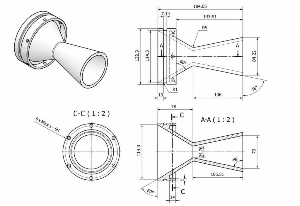
The drawing conveys more information than simply defining feature sizes. It also includes tolerances, surface finish, thread, material, and inspection details. Understanding the dimensions is not sufficient to know how the part is to be produced.
When the program is written, engineers examine the entire drawing to determine what features are to be controlled further. This review allows them to choose appropriate tooling, sequence the machining process, determine inspection points, and minimize changes during the production process.
Typical Aerospace CNC Machining Tolerance Ranges
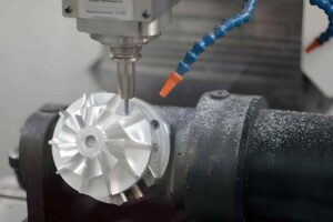
The exact tolerance always comes from the engineering drawing, but many aerospace components follow similar machining capabilities during production.
The values below represent common ranges used for different machining operations. Engineers still adjust these values according to the part function, material, and assembly requirements.
| Feature/Machining Operation | Typical Tolerance Range | Typical Aerospace Applications |
| General CNC milling | ±0.05 to ±0.10 mm | Mounting brackets, equipment covers, structural supports |
| Precision CNC milling | ±0.02 to ±0.05 mm | Electronic housings, machined frames, instrument mounts |
| Precision turned diameters | ±0.01 to ±0.03 mm | Shafts, sleeves, bushings, spacers |
| Precision bores (boring / reaming) | ±0.005 to ±0.02 mm | Bearing bores, locating holes, dowel holes |
| Ground diameters | ±0.002 to ±0.01 mm | Bearing journals, spindle seats, precision shafts |
| Precision flat surfaces | Flatness within 0.01 to 0.03 mm | Sealing faces, mounting interfaces, reference surfaces |
| Threaded holes | Thread class specified on the drawing (ISO 6H / Unified Class 2B or 3B are common) | Fastener holes, threaded inserts, structural joints |
| Hole position (GD&T) | 0.02 – 0.10 mm | Dowel holes, locating features, assembly interfaces |
Please Note: These are typical production capability ranges used in precision CNC machining. The final tolerance is always defined by the:
- Engineering Drawing
- GD&T Requirements
- Customer Specifications
- Function of the Feature
Which Standards Define Aerospace Tolerances?
The drawing is rarely the only document that you read before you begin to program an aerospace part. In most jobs, the drawing will be accompanied by quality requirements, GD&T, customer specifications, and inspection documents.
AS9100 Requirements
Usually, aerospace customers require suppliers to provide parts under their quality system AS9100. This standard doesn’t specify the tolerances to be used; it manages the planning, recording, and checking of the work during production.
If you make the structural bracket, for instance, the size of the finished bracket might not be enough for the order.
The customer might also ask for material certificates, in-process inspection documents, First Article Inspection (FAI) documents, and full traceability of the finished part. Requirements are incorporated into the manufacturing process, starting at the first operation rather than at the end of machining.
GD&T Standards
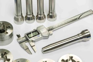
All sizes are drawn to scale – and sometimes you can make all these measurements and still get a rejected part. This typically happens when the size is appropriate, but the feature is not found, aligned, and oriented within the tolerance.
So, GD&T is used in an aerospace drawing, in conjunction with dimensions. A locating hole is an example. The diameter can be within the specified size; however, if the hole drifts a little off center from what is required, the mating piece will not fit during assembly. These relationships are controlled by GD&T, which means that the inspection process is aligned with the use of the part.
Customer Specifications
The engineering drawing simply describes the part appearance, and customer specifications may describe manufacturing and part inspection. There are other requirements for accepted materials, inspections, measurement reports, special processes, marking, packaging, and documentation that you may find.
Engineers do not review these documents individually, but compare them with the drawing before the machining process starts. Early review can identify additional inspection areas, special quality requirements, and documentation required before acceptance of the part.
How Do Aerospace Materials Affect Tolerance Control?
How easily you can maintain the tolerance you’ve set depends on the material you are machining. Some materials are machined with relative ease, while others may generate more heat, wear cutting tools more rapidly, and require more inspection.
Engineers typically check the drawing and the material during the planning stage to machine, since not all aerospace alloys are appropriate for the same machining process.
Aluminum Alloys
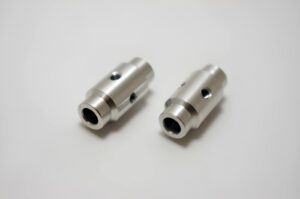
Aluminum is a lightweight yet strong material. It is one of the most widely used materials in the aerospace industry due to its smooth cutting and stability. Even on the lightest metals, material removal can cause large pockets, thin walls, and long ribs to move slightly.
So, machinists often leave a small amount of material after rough machining. The final pass removes this remaining material after the part has stabilized. This approach helps produce the critical dimensions more accurately.
Titanium Alloys
The machining behavior of titanium differs from that of most common engineering metals. It concentrates heat around the cutting edge. This leads to faster tool wear than machining aluminum.
Holes, slots, and other precision features may slightly change in size as the tool wears. That is why manufacturers check key dimensions more frequently and change tools before they start to impact the finished part.
Stainless & Superalloys
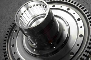
The higher the cutting force, the more difficult it is to cut stainless steel and nickel alloys. During long machining processes, tool wear becomes more evident.
Therefore, manufacturers often split the roughing and finishing operations, rather than attempting to complete one operation in one pass. This allows for more control over final dimensions.
Composite Components
Composite materials contain a fiber layer and resin. So, the parts must be precisely machined differently than metal. Many composite parts are subsequently joined with metal parts, so hole size and location of features still must match the drawing before the part can proceed to assembly.
Which Features Require the Closest Control?
Not all features of an aerospace part are inspected equally. The features that impact assembly, alignment, sealing, and part movement are analyzed first. These areas are typically checked again during manufacturing since the next manufacturing process may be affected by a slight dimensional deviation.
Precision Holes
Pins, bushings, bearings, and fasteners are frequently placed in precision holes when assembled. If the hole size is right but the placement is off, it is possible that the mating piece will not fit as expected.
Generally, these holes are checked after the machining process rather than after the part is finished. This way, any adjustments can be performed prior to the other features being cut.
Bearing Seats
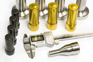
The diameter and the finished surface should be the same as the drawing when the rotation parts are supported by bearing seats. The bearing fit may vary when installing a slightly oversized, undersized, or out-of-round seat.
Therefore, the bearing seats are often finish-machined at the very end and inspected before the next step in the process.
Mating Surfaces
Many components in the aerospace industry are assembled with a second machined part. These surfaces are flatter, aligned, and located to help position the whole assembly properly, and are usually examined after completion to set the groundwork for other components when they are put together.
Threaded Features
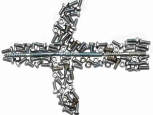
At the outset, a threaded hole might seem a simple component, but it is still vital enough to warrant careful examination on an aerospace part.
Thread size, depth and position must all correspond to the drawing. Otherwise, bolts, inserts and fittings will not fit without further effort.
Threaded holes are typically checked for quality and location at the manufacturing stage before the part is sent for inspection if it is used in precision assemblies, hydraulic fittings or structural applications.
How Are Aerospace Tolerances Achieved During CNC Machining?
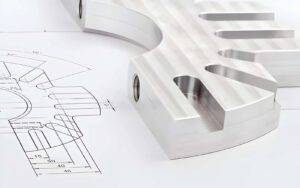
Typically, holding ideal aerospace tolerances requires numerous small checks, not just one. The setup, cutting tools, order of parts to be machined, and inspection procedure are all covered before the first production part is accepted.
Manufacturers adjust the process if one stage lags while the rest of the features are still being manufactured.
Machine Capability
A stable machine setup provides the machining process with a consistent starting point. Engineers verify that the workholding assures proper support of the part and the machining datum is consistent with the engineering drawing before production starts.
This preparation is even more critical in larger aerospace parts as the same setup must be stable throughout the machining cycle.
Tool Condition
As production continues, cutting tools are likely to start to wear. The change is usually small, but it typically shows up on precision holes, finished diameters, and bearing locations.
Manufacturers plan to replace tools, instead of waiting until they are inspected, to ensure critical features are controlled.
Temperature Control
During machining, heat is constantly produced. Heavy roughing operations pose different conditions than light finishing passes; therefore, critical measurements are normally taken after the component has reached a stable condition.
Process Verification
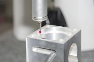
The inspection starts as soon as the part is made. Precision bores, holes to be located, bores to be sealed, etc., are frequently measured following the operation that creates them.
If one dimension starts to get out of the drawing specification, the machining process can be adjusted before the rest of the process.
What Documentation Is Required For Aerospace Machined Parts?
Typically, customers from the aerospace sector request documentation when the part is delivered. The records provide details of the material used, inspected, and the flow of the part through the production process. Requirements for documents are dependent on the drawing and the quality requirements of the customer.
Material Certificates
Material Certificates are used to verify the raw material quality. These also contain the batch information and the test results from the material supplier. These certificates ensure that the appropriate material went into the production process.
Inspection Reports
Measurements taken by inspection during the machining and final inspection are documented. They indicate which features have been measured and whether or not these features match the drawing.
A First Article Inspection (FAI) report is also needed for many aerospace components before the initiation of regular production.
Traceability Records
Traceability records create a clear link between the finished component, the material used, the machining process, and the inspection records. Later, when a customer requests production information, these records provide easy access to that information.
Identification and tracking are performed within each part throughout the manufacturing process.
Process Documentation
A process document is used for documenting the manufacturing stages of a part from start to end. May contain machining operations, inspection stations, special processes, and quality records required for the job. These documents give a clear production history before shipping to the customer.
What are the Common Causes of Tolerance Variation In Aerospace Parts?
The final part dimensions can vary, even if the same drawing and CNC program are employed. The variations evolve due to material movement, tooling, set-up, and machining parameters.
Material Movement
The stability of aerospace parts reduces with removal of material. Thin walls, deep pockets, and large openings can be the cause of a slight movement in the part before the final machining pass.
Manufacturers sometimes rough machine the part to prevent this, and then complete the final operations once the part is more stable.
Tool Wear
After several cutting operations, the material removal process of a cutting tool differs from the first material removal process. With the use of the cutting edge, dimensions may start to change gradually, particularly with precision holes and finished diameters.
During the manufacturing process, the machine is maintained with regular tool checks and planned tool replacement, which helps to maintain the machining process consistency.
Fixture Setup
How a part is held for machining directly affects the dimensions. When the workpiece is not supported properly, it may move while it is being cut and impact the location of related parts. The setup is verified before machining to ensure the part is held in position during machining.
Thermal Changes
When material is removed, the heat accumulates particularly over lengthy cycles. If measurements are taken on the part immediately after it is cut, it may not be the same size as after it has cooled.
Design Practices That Improve Manufacturability
A well-prepared drawing makes machining and inspection much easier. Clear dimensions, practical GD&T, and reasonable surface finish requirements help manufacturers plan the process before production starts. This also reduces questions during machining and inspection.
Practical Dimensions
Dimensions should clearly define the finished feature without adding unnecessary values. A simple and complete drawing is easier to program, machine, and inspect.
Avoid repeating dimensions that describe the same feature. Clear dimensioning also reduces the chance of measurement differences during production.
Functional GD&T
Apply GD&T only to features that affect assembly and part function. Not every surface needs additional geometric controls.
Using GD&T on the right features keeps the drawing clear and allows inspectors to focus on the areas that need closer verification.
Surface Finish
Specify a surface finish only where the part function requires it. Bearing seats, sealing faces, and sliding surfaces often need a controlled finish, while many other machined surfaces can use the finish produced by the machining process.
This approach avoids extra machining that adds time without improving the finished part.
Inspection Access
Inspection becomes easier if measuring points can be reached without difficulty. Leave enough space around important holes, bores, and reference surfaces so measuring equipment can contact the feature properly.
Aerospace CNC Machining Capabilities at YD Rapid
At YD Rapid, we machine aerospace parts according to your engineering drawing and project requirements. Our team reviews the material, dimensions, GD&T, surface finish, and inspection requirements before production begins.
We support aluminum, titanium, stainless steel, superalloys, and engineering plastics, and provide dimensional inspection, material certificates, FAI, and traceability records whenever your project requires them.
Ready to start your project? Upload your drawing today, and our engineering team will review your design, answer your questions, and provide a detailed CNC machining quotation.
FAQs About Aerospace CNC Machining Tolerances
What tolerance is typical for aerospace CNC machining?
There is no fixed aerospace tolerance. Each feature receives a tolerance that matches its job on the finished part. Precision holes and bearing seats usually have closer limits than general machined surfaces.
Which aerospace standard defines machining tolerances?
The engineering drawing defines the required tolerances. AS9100 supports the quality system, while GD&T standards define feature location, orientation, and form. Customer drawings may also include additional requirements.
Why are aerospace tolerances stricter than industrial parts?
Many aerospace parts fit directly with other precision components. Small dimensional changes can affect assembly, so important features receive closer control during machining and inspection.
How are aerospace tolerances inspected?
Critical features are measured during machining and again after the part is finished. Manufacturers use CMMs, gauges, micrometers, and other measuring equipment according to the drawing requirements.
What is First Article Inspection?
First Article Inspection (FAI) checks the first completed part before regular production begins. It confirms that the part matches the engineering drawing and project requirements.
Which aerospace materials are more challenging to machine?
Titanium alloys, stainless steels, and nickel alloys usually require more machining control than aluminum. These materials increase tool wear and often need more frequent inspection during production.
Does GD&T replace dimensional tolerances?
No, dimensions define the feature size, while GD&T controls its position and geometry. Both are used together on aerospace drawings.
Can every feature use the same tolerance?
No, different features perform different jobs, so they often have different tolerance requirements. Engineers apply closer control only to the features that affect assembly and part function.