If you’ve ever looked at a machining drawing and wondered how every feature could be produced without repositioning the part several times, that’s usually the point where 5-axis machining enters the discussion. It isn’t selected because the machine has more movement. It is selected because the part becomes easier to machine.
Think about an impeller, a turbine blade, or a mold insert. These parts contain features that point in different directions. Even many of them are difficult to reach with a standard vertical machining center. Re-clamping the workpiece after every operation adds time and creates another setup that must be checked before machining continues.
A 5-axis machine integrates rotary movement with the standard X, Y, and Z axes; it reaches more surfaces without repeatedly moving the workpiece.
This guide explains how 5-axis milling works, the machine configurations used in production, the types of components commonly machined, and the design decisions that help simplify manufacturing before the first cutting tool enters the material.
What Makes a Machine “5-Axis”?
In 5-axis CNC machining, the cutting tool can approach the workpiece from multiple directions, reducing setups and improving access to complex features.
A standard CNC milling machine uses three linear axes to position the cutting tool. A 5-axis machine adds two rotary axes, giving the machine more freedom to approach the workpiece from different angles.
The extra movement allows more surfaces to be machined in fewer setups, although the machine layout determines how the rotary axes move during production.
The Three Linear Axes (X, Y, and Z)
The three basic movements used in CNC Milling are the X axis, the Y axis, and the Z axis. The X axis is used to move the machine left and right, the Y axis is used to move the machine forward and backward, and the Z axis is used to move the cutting tool up and down. Features formed by these three axes include flat surfaces, slots, pockets, holes, and profiles.
Two Rotary Axes (A, B, C)
A 5-axis machine provides two rotary movements in addition to the three linear movements. Depending on the machine configuration, rotation takes place through the worktable, the spindle head, or a combination of both. These extra movements enable the cutting tool to reach angled faces and complex surfaces without the need to re-position the part in the machine.
Simultaneous 5-axis vs 3+2 Positional Machining
Positional machining is a 3+2 process that positions the work at a fixed angle before cutting. The next machining process involves the X, Y, and Z axes.
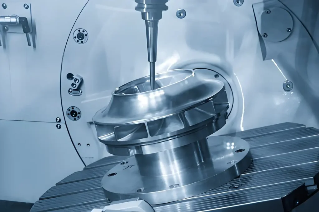
During simultaneous 5-axis machining, all five axes are controlled during the machining process, which is ideal for impellers, turbine blades, mold cavities, and other complex surfaces.
Common 5-Axis Machine Configurations
Not every 5-axis machine is built the same way. The difference comes from which part of the machine rotates during machining. Some machines rotate the worktable, some move the spindle, and some use both. The best choice depends on the size, weight, and shape of the workpiece.
Trunnion-Style Machines
The trunnion machine has a table that tilts and rotates the workpiece. It is ideal for smaller parts as the machine can access several faces without removing the part. They are typically used in the production of mold inserts, medical parts, or precision mechanical parts.
Swivel Head Machines
The spindle adjusts its cutting angle as the swivel head machine holds the workpiece in place. This simplifies the machining of larger and heavier components that might not be possible to rotate on a table. It is commonly used to create large molds, aerospace structures, and machine parts.
Table-Head Machines
It is a combination of a rotating table and a swiveling spindle. Distributing the movement between both parts of the machine provides better access to complex features and different machining angles. It is frequently utilized for parts that have multiple faces that are machined and detailed geometry.
Comparison Table
| Configuration | Rotary Movement | Common Applications | Limitation |
| Trunnion-Style | Rotating and tilting table | Small precision parts, mold inserts, medical parts | Limited part size and weight |
| Swivel Head | Rotating spindle head | Large molds, aerospace parts, heavy components | More complex machine structure |
| Table-Head | Rotating table and swiveling spindle | Complex multi-face parts, precision components | Higher machine cost |
Parts That Are Produced from 5-Axis CNC Milling
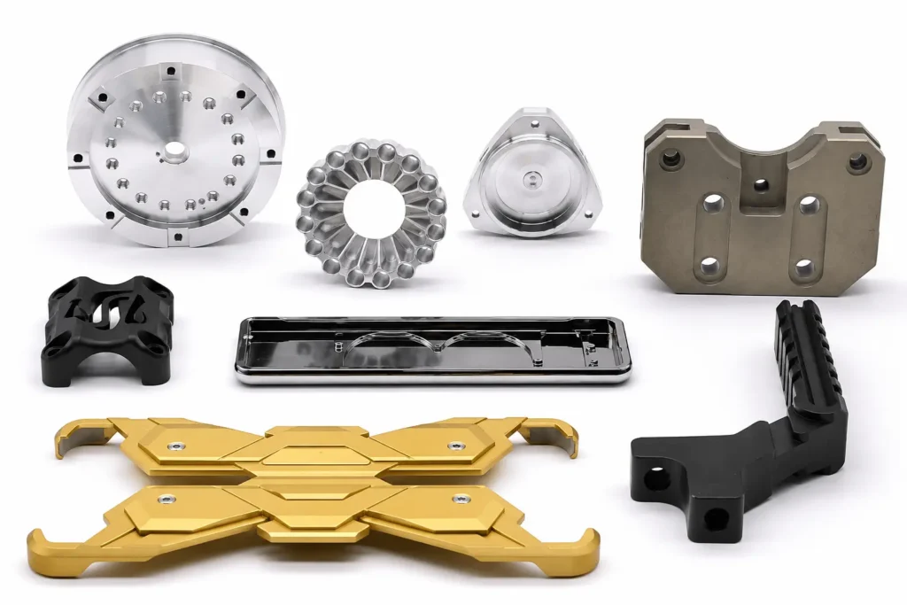
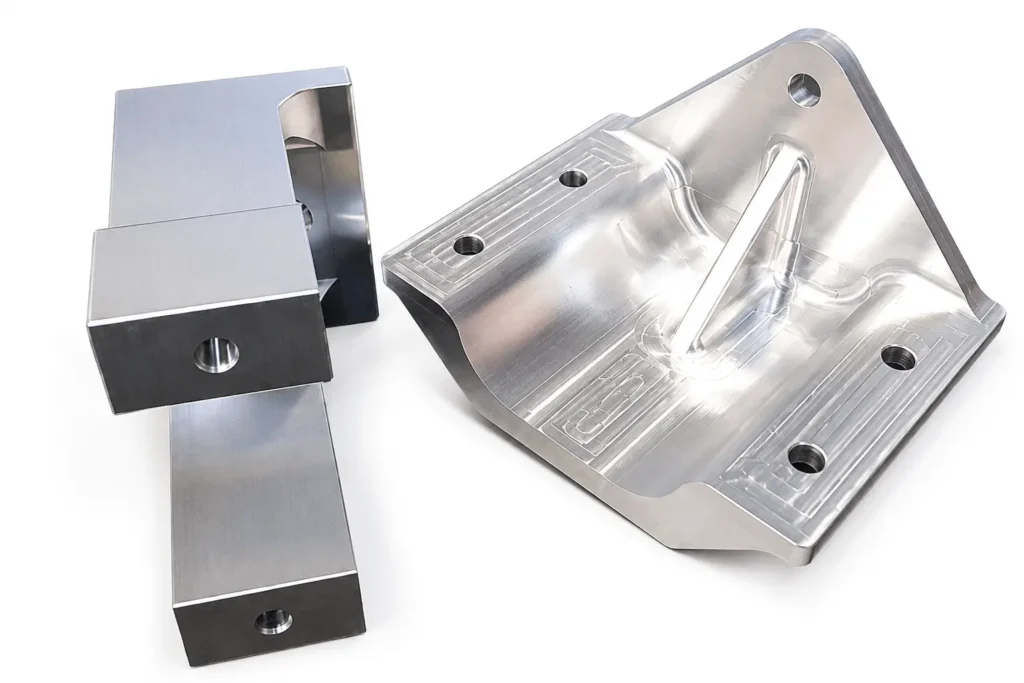
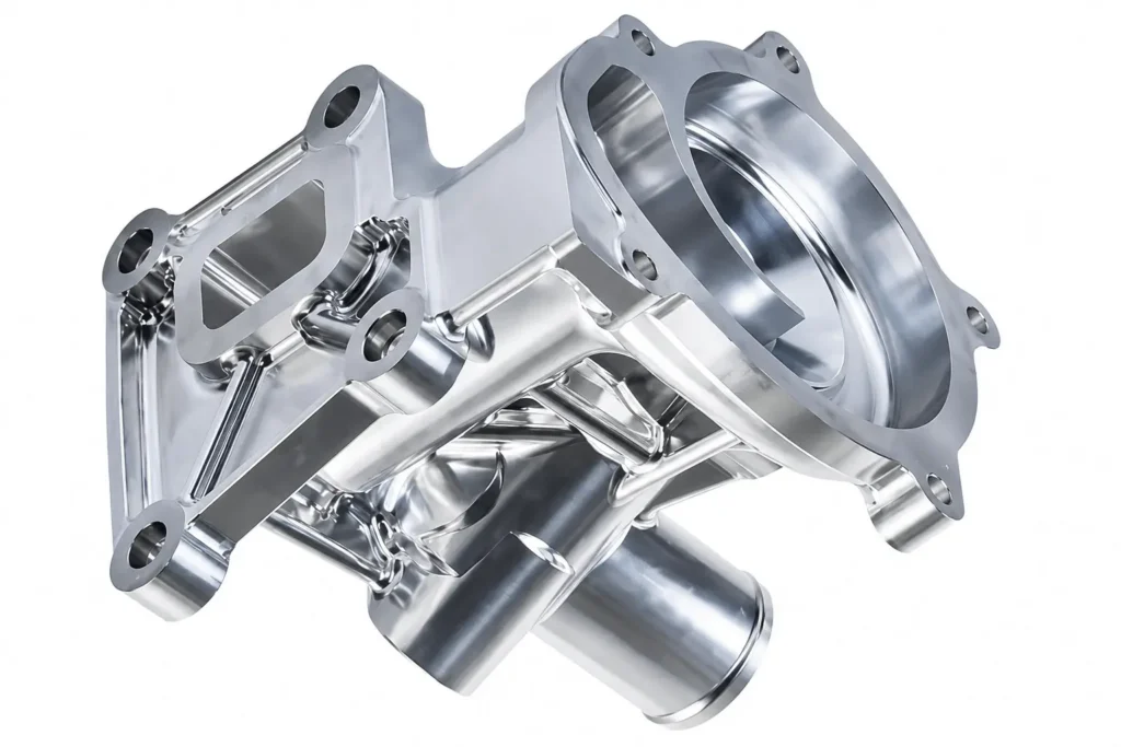
Compared with conventional CNC milling, 5-axis machining is better suited to parts with angled surfaces, deep cavities, compound curves, and features on multiple sides.
A 5-axis machine is selected because of the part geometry, not simply because it has more axes. Components with features on several faces, difficult cutting angles, or limited tool access are often better suited to this machining approach.
Multi-Face Components
Machining on 4 or 5 sides is necessary to create mounting faces, threaded holes, pockets, and locating features on some parts. These surfaces can be reached with only a few setups using a 5-axis machine, which simplifies the maintenance of the required relationship between each of the surfaces being machined.
Complex Curved Surfaces
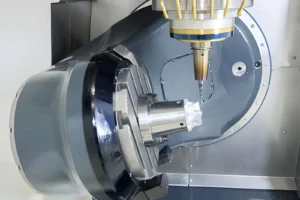
Cutting a freeform geometry needs the cutting tool to change angles as it cuts. Common applications include turbine blades, impellers, orthopedic parts, and aerospace parts that all require greater access to the tool when milling across the surface of the part.
Deep Cavities and Tall Walls
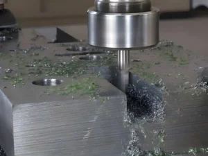
The cutting tool space is restricted by deep cavities and tall walls. A 5-axis machine allows the spindle to be tilted toward the cutting area, lessening the need for the use of very long tools and freeing up access inside the workpiece.
Precision Mold and Die Components
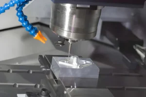
Complex cavity surfaces, deep ribs, and detailed contours are common features in injection molds, die-casting molds, forging dies, and stamping dies. The 5-axis machine is better suited to reach these areas, minimizing extra setups when manufacturing the mold.
Design Tips Before 5-Axis CNC Machining
A 5-axis machine can machine complex geometry, although the part design still influences cutter selection, machining strategy, and programming. Reviewing a few design details before production often avoids unnecessary machining challenges.
Leave Enough Tool Clearance
Inspect the area around all pockets, walls, and interior elements. The cutter is required to cross into the machining area and execute the tool path without coming into contact with surfaces nearby. A smaller clearance will require a smaller cutter and thus more cutting passes.
Avoid Deep Narrow Cavities
The depth of a cavity is far greater than its diameter, and influences the choice of cutters. Long end mills may be needed, but these will cut less per pass than those of lesser length. The wider the opening is made or the shallower the unnecessary depths, the more options the programmer has in the way that the part can be machined.
Avoid Deep Narrow Cavities
All internal corners are formed using a round cutter, and thus the corner radius should be of a standard tool size. The smaller the radius, the fewer cutters that can be used, and the narrower end mills will be; the more passes it will take to machine the same material.
Apply Tolerances Where They Add Value
Check all the tolerances before production. Many dimensions can be taken to standard tolerances in the process without impacting the final product, but features requiring assembly, bearing fits, sealing surfaces and/or alignment will typically require closer tolerances.
Material Selection for 5-Axis CNC Milling
The same machining program cannot be applied to every material. Cutting speed, cutter selection, spindle load, and machining strategy are adjusted according to the material being machined.
Aluminum Alloys
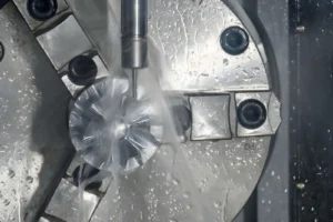
Aluminum is frequently used for parts that have complex geometry due to its ability to withstand high spindle speed and material removal rates. Examples include prototype parts, heat sinks, housings, and aerospace brackets. Grades such as 6061-T6, 7075-T6, and 2024 are widely machined on 5-axis equipment.
Stainless Steel
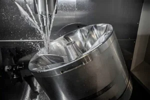
The cutting technique for stainless steel is different from that of aluminum. The austenitic grades (304 and 316) produce more heat during machining operations, and the precipitation-hardened grades (17-4 PH) are often employed for parts that must be stronger.
Titanium Alloys
Common applications of titanium manufacture are in aircraft structures, turbine parts, and medical implants. The cutting speed and stability of the tool engagement are usually smaller in titanium machining. Titanium has less heat dissipation effect in the cutting edge area, so it is not suitable to use high cutting speed for the machining process.
Tool Steels
P20, H13, D2, and other tool steels are often used in the manufacture of injection molds, forging dies, and stamping tools. Rough machining is usually performed before heat treatment, and finishing operations are done following heat treatment to obtain the desired dimensions and surface finish.
Engineering Plastics
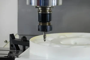
5-axis machines can also process several engineering plastics, including PEEK, POM (Delrin), Nylon, PTFE, and UHMW-PE.
The materials are frequently employed in electrical insulation, wear parts, medical applications, and lightweight mechanical parts. When machining plastic, the workholding is given attention since some plastics can be deformed if they are clamped too tightly.
Material Overview
| Material | Common Grades | Typical Components |
| Aluminum Alloys | 6061-T6, 7075-T6, 2024 | Aerospace parts, housings, fixtures |
| Stainless Steel | 304, 316, 17-4 PH | Medical, food processing, industrial parts |
| Titanium Alloys | Ti-6Al-4V (Grade 5) | Aerospace, implants, turbine parts |
| Tool Steels | P20, H13, D2 | Injection molds, dies, tooling |
| Engineering Plastics | PEEK, POM, Nylon, PTFE, UHMW-PE | Insulators, wear parts, medical components |
How to Decide Whether Your Part Needs 5-Axis Milling
The drawing usually provides enough information to determine whether 5-axis machining is necessary. Reviewing the part geometry, feature locations, and machining requirements before production helps identify the most suitable machining approach.
Parts Suitable for 3-Axis Milling
Many components don’t need to move in multiple axes at once. For parts with simple geometry and which can be machined with a few setups, a 3-axis machine can be more practical. During the design review process, think about the following questions:
- Is most of the feature found on one face?
- Do all the other features fit into the same simple setup to be machined?
- Are the features primarily pockets, slots, holes, and flat surfaces?
- Is it possible to use standard length cutting tools throughout the machining areas?
- Do not have compound angles or freeform surfaces.
Parts That Benefit from 5-Axis Milling
Several part geometries make use of the ability of the cutting tool to attack the workpiece from multiple angles, thereby greatly facilitating part machining. Here are some questions to consider to see if a 5-axis machine can give a better machining solution:
- Is there more than one face containing machined features?
- Are there holes or machining surfaces that are not parallel or perpendicular to the page?
- Do there exist deep cracks with high walls?
- Is there a continuous curved surface in the part?
- Would there be a need for multiple setups on a 3-axis machine?
If there is a need for critical features to be aligned across several faces, do they require the correct alignment?
Engineering Review Before Production
Before selecting the machine, the engineering team reviews the drawing to confirm that the machining process matches the part requirements. The following questions are commonly considered before programming begins:
- Can the part be completed in one setup?
- Which 5-axis machine configuration best suits the part?
- Can every feature be reached with standard cutting tools?
- Are the specified tolerances practical for the application?
- Does the selected material require a different machining strategy?
- Can the same result be achieved with a simpler machining process?
3-Axis vs 4-Axis vs 5-Axis Milling: What’s the Difference
The number of machine axes affects how a part is machined, how many setups are needed, and the types of features the machine can produce.
The comparison below highlights the main differences between 3-axis, 4-axis, and 5-axis milling, making it easier to match the machining process to your part requirements.
| Feature | 3-Axis Milling | 4-Axis Milling | 5-Axis Milling |
| Machine Axes | X, Y, Z | X, Y, Z + 1 rotary axis | X, Y, Z + 2 rotary axes |
| Rotary Motion | None | Single rotary axis | Two rotary axes |
| Workpiece Positioning | Multiple manual setups | Indexed or continuous rotation on one axis | Indexed (3+2) or simultaneous 5-axis machining |
| Complex Surface Machining | Limited | Moderate | Excellent for freeform surfaces |
| Multi-Face Machining | Several setups | Fewer setups | Often completed in one setup |
| Typical Applications | Plates, brackets, simple housings | Cylindrical parts, indexed features | Impellers, molds, aerospace, medical parts |
| Setup Requirements | Highest | Moderate | Lowest |
5-Axis CNC Milling Services at YD Rapid
Choosing 5-axis machining starts with understanding the part, not simply selecting a machine. At YD Rapid, every project begins with an engineering review of the drawing to determine the most suitable machining approach. If design changes could simplify machining or reduce unnecessary cost, our team provides free DFM feedback before production starts.
As an ISO-certified manufacturer, we provide 5-axis CNC milling for aluminum, stainless steel, titanium, tool steels, and engineering plastics. From a single prototype to full production, every project follows the same engineering review and manufacturing process.

Upload your CAD files to receive a fast quotation and manufacturing support from prototype to production.
FAQs
What is the difference between 3-axis and 5-axis milling?
A 3-axis machine moves along the X, Y, and Z directions, while a 5-axis machine adds two rotary movements. The additional axes allow the cutter to approach the workpiece from different angles, reducing the need for repeated setups on complex parts.
Does every part need 5-axis machining?
Generally, 3-axis machines are used to machine simple brackets, plates, covers, and other parts. A part with more than one machined face, compound angle, deep cavities, or freeform surfaces is better suited for 5-axis machining.
Is 5-axis milling more accurate than 3-axis?
The accuracy of the machining is determined by the condition of the machine, tooling, programming, and inspection process. More features in one machine setup might help to keep the positional relationship among the features machined.
What is simultaneous 5-axis machining?
Simultaneous 5-axis machining keeps the three linear axes and two rotary axes moving throughout the cutting operation. It is often used to produce impellers, turbine blades, mold cavities, and other complex surfaces.
Which materials can be machined on a 5-axis CNC machine?
Common materials include aluminum alloys, stainless steel, titanium alloys, tool steels, brass, copper, PEEK, POM, PTFE, Nylon, and many other engineering plastics.
Can 5-axis milling reduce production time?
Parts that require machining on multiple faces often require fewer setups on a 5-axis machine. Reducing setup changes can shorten the overall machining process, particularly for complex components.
Is 5-axis machining suitable for prototypes?
Prototype machining is widely used to verify part geometry, assembly, machining strategy, and surface finish before moving into production.
How do I know if my part requires 5-axis milling?
The drawing provides the best starting point. Feature locations, machining angles, tool accessibility, workpiece size, and setup requirements are typically reviewed before selecting the machining process.