CNC turning time is made up of several steps. The tool has to remove the stock, change tools, move between features, and the part has to be loaded and removed. If one of these steps takes longer than necessary, the total cycle becomes longer.
For example, a turning pass at 1,000 RPM and 0.25 mm/rev gives a feed rate of 250 mm/min. With a 100 mm cutting length, the cutting time is about 24 seconds. Increasing the feed to 0.30 mm/rev brings it down to about 20 seconds, provided the insert and workholding can handle the change.
This article covers cycle-time calculation, cutting parameters, roughing, tooling, toolpaths, workholding, part design, and production delays. The focus is on finding the time used by each step and reducing it where the process allows.
What Makes Up a CNC Turning Cycle?
There are two forms of machining time in a CNC turning cycle: cutting and moving/handling the part. Set-up time is excluded as this is usually done prior to production.
Cutting Time
Cutting time is the time that the tool is actually engaged in the workpiece. It consists of rough turning, facing, boring, grooving, threading, and finishing passes.
Here is an approximate formula for the cutting time in a straight turning pass:
Time = length of cut / Feed rate
For example, if the length of turn is 100 mm, the feed is 0.25 mm/rev, and the spindle speed is 1,000 RPM, a 100 mm turning length at 0.25 mm/rev and 1,000 RPM will result in:
Feed rate = 0.25 × 1,000 = 250 mm/min
Cutting time = 100/250 = 0.4 min = 24 seconds
The cutting time increases with every pass.
Non-Cutting Time
Non-cutting time is the time that is not spent removing material. It features turret indexing, quick positioning, tool approach, retracts, and part transfer.
The times are from the CNC program and machine operation. For instance, if the turret indexes 6 tools and every tool change takes 1.5 seconds, the indexing will consume 9 seconds if each tool is changed.
The cycle can then be reduced without the cutting speed changing by minimizing unnecessary indexes and long positioning moves.
Setup and Loading Time
Setup time is defined as the time required for tool setting, work offset setting, chuck or collet setup, program proving, and first piece checks. It is usually treated separately from the end cycle time of each finished product.
Loading time applies to each part in a manually loaded process. The operator’s handling time and machine production time are 15 seconds per part for loading and unloading and 60 seconds per part for a 45-second machining cycle.
This handling time can be reduced by bar feeding or by using automatic part ejection for higher-volume production. The saving should be based on the real loading operation and not on the loading equipment alone.
How Do You Calculate CNC Turning Cycle Time?
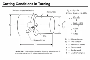
Cycle time is determined on an operation-by-operation basis. Use the actual toolpath length and feed, plus the time for tools to change and for toolpaths to include non-cutting moves. This provides an approximation for production planning to be used.
Turning Time
The programmed cutting length and feed rate should be used for straight turning.
Time = Cutting length / Feed rate
Given that the tool takes 120 mm at 0.25 mm/rev and the spindle rotates at 1,000 RPM:
Feed rate = 0.25 × 1,000 = 250 mm/min
Cutting time = 120 ÷ 250 = 0.48 min = 28.8 seconds
When cutting speed is given instead of RPM, then calculate spindle speed based on the workpiece diameter:
RPM = (Vc × 1000) ÷ (π × D)
When performing production work, do not use a common cycle time value for all operations, but rather the cycle time value that has been programmed for the specific operation.
Facing Time
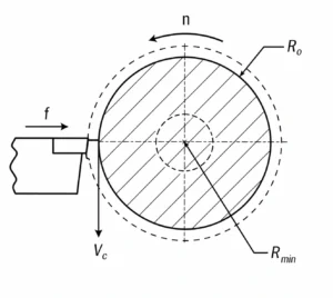
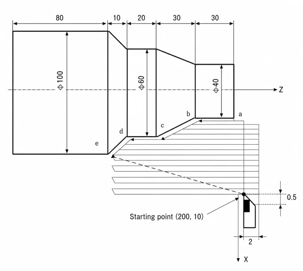
Facing is measured from the travel of the tool on the radial plane.
At 0.20 mm/rev and 1,000 RPM, a 50 mm diameter face will travel approximately 25 mm as the tool moves from outside to inside.
Feed rate = 0.20 × 1,000 = 200 mm/min
Cutting time = 25 ÷ 200 = 0.125 min = 7.5 seconds
Approach, retract, and dwell programmed for the cycle must be added separately.
Multiple Roughing Passes
It may be necessary to rough several times. Find the time taken for each lap and sum them up.
For example:
Pass 1: 24 s
Pass 2: 24 s
Pass 3: 24 s
Pass 4: 24 s
The total time of roughing = 96 seconds
The roughing time is now 72 seconds, resulting in a 24-second saving per part since the same stock can be removed in three passes at an acceptable cutting load.
The helpful analogy is not just “more passes vs. fewer passes. Before decreasing the number of passes, confirm the depth of cut, insert load, machine power, and remaining stock.
Complete Cycle Example
A simple turned component may have the following programmed times:
| Operation | Time |
| Rough turning | 72 s |
| Facing | 8 s |
| Finishing | 20 s |
| Threading | 16 s |
| Tool indexing | 6 s |
| Rapid movements | 8 s |
| Total cycle | 130 s |
The estimated machining cycle is therefore 130 seconds per part, excluding manual loading and unloading.
This breakdown also shows where the time is going. If roughing accounts for 72 seconds, changing a 6-second tool-indexing step will have little effect compared with improving the roughing operation.
How Do Cutting Parameters Affect Turning Productivity?
Cutting speed, feed, and depth of cut directly affect how quickly a CNC lathe removes material. Each value should be set from the material, insert manufacturer’s data, machine capacity, and actual cutting conditions.
Cutting Speed and Spindle RPM
Cutting speed is the surface speed at the workpiece. Calculate spindle speed with:
RPM = (Vc × 1000) ÷ (π × D)
For example, at 200 m/min on a 50 mm diameter, the spindle speed is about 1,273 RPM.
The RPM will vary when the diameter is changed. That’s where constant surface speed is helpful when operating on parts with varying diameters.
Feed per Revolution
The Feed per revolution is the distance that the tool will travel in one revolution of the spindle.
Feed rate = RPM x Feed per Revolution
For example, at 1,000 RPM and 0.25 mm/rev:
Feed rate = 250 mm/min
As the feed is increased, the cutting time is decreased unless the cutting load is too great for the machine, material, surface requirement, and insert.
Depth of Cut
The amount of material removed radially in one cut is called the depth of cut. The more, the merrier, the larger the DOC, the less will be the roughing passes.
When removing radial stock 6 mm or more:
2 mm DOC: 3 passes
3 mm DOC: 2 passes
Choose the depth of cut (DOC) based on the insert manufacturer’s recommended range and the machine’s power and setup rigidity. Deeper cuts are suitable only when the tooling and setup can handle the additional cutting load.
Material Removal Rate
The material removal rate indicates the amount of material removed per minute. It can be estimated with the following methods for turning:
MRR = π × D × DOC × Feed rate
MRR is also suitable for the comparison of roughing conditions. If the feed and DOC are low, then a higher RPM does not necessarily translate to a greater output.
When planning production, consider the cutting speed, feed, DOC, and the resulting MRR as well as spindle RPM.
How Can Tool Selection Reduce Turning Cycle Time?
The tool will impact cycle time primarily by the volume of stock removal per pass and by the number of tools needed for the part. The choice of tooling should be based on the feature and cutting data rather than vice versa.
Insert Geometry
For heavy stock, use a roughing insert, and for a final surface, use a finishing insert. They have different cutting edges and recommended cutting parameters.
When grooving, try to fit the width of the inserts into the groove if possible. If a suitable 3 mm grooving insert can be used to produce the feature, then a 3 mm groove does not require several side passes.
DOC, feed, and cutting speed should be taken from the insert manufacturer’s data. These values have a direct effect on cycle time.
Tool Selection for Specific Features
Certain features can’t be done efficiently using a standard OD turning tool. An internal diameter must use a boring bar. The thread form is done using a threading insert. A grooving insert is used for narrow internal and/or external grooves. Profiling equipment is chosen based on the contour and access.
The reality is that you don’t want to make one tool do the task of another tool. That can add additional passes and add cutting time.
Tool Life vs. Cycle Time
Not all of the shortest single part cycle is necessarily the lowest production time. Suppose one of the cutting conditions yields 60 seconds per cycle and 40 parts per edge; another yields 56 seconds per cycle and 15 parts per edge. The second condition saves time while cutting, but requires the inserts to be changed more often.
When producing, consider cycle time in conjunction with parts per edge and insert-change time. The best setting is the setting that provides a helpful cycle without making unnecessary tool changes.
How Does Workholding Affect CNC Turning Output?
The workholding method affects the time between parts. Loading, clamping, part transfer, and unloading can add significant time outside the actual cutting cycle.
Chuck vs. Collet
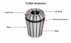
A chuck is generally used for parts that have a larger diameter, short blanks, castings, forgings, and parts not supplied in continuous bar.
A collet is better for reworking from bar stock within the clamping range. The bar can be set, clamped, and then either machined or moved to the next cycle.
The practical choice depends on the shape of the parts, the form of the stock, and the quantity of parts. A chuck provides greater flexibility, while a collet type is more appropriate for repeated bar-fed operations.
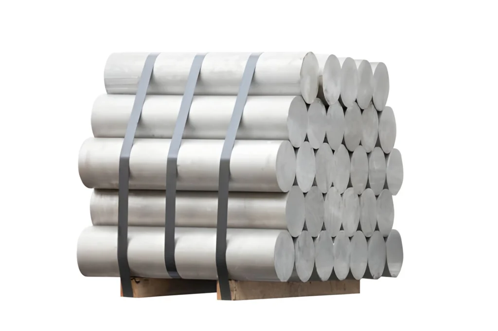
Bar Stock and Bar Feeding
There is a bar feeder that feeds it through the spindle, so that the operator does not have to load the individual blank after finishing each part.
The machine cuts the exposed length and then separates the part from the bar, ready for the next cycle. This eliminates the repetitive loading operation from the production process.
This type of setup is suitable for parts that can be manufactured from standard bar stock and have sufficient production volumes to warrant the feeder setup.
Part Transfer
Machining parts that have to be machined at both ends usually requires a second holding operation. The completed first side can be moved on a machine with a sub-spindle to the second side for machining.
This eliminates the need to unload the part and turn it over for reloading.
The automatic part ejection is based on the same principle. After machining is done, the part is taken away from the working area, so that the next cycle can be taken up with less manual handling.
How Can CNC Turning Toolpaths Reduce Idle Time?
Not all cycle time comes from cutting. It also takes time to move from one feature to another, to index, and from the part. The following moves must be verified in the CNC program: these moves can increase the part building time without providing any value.
Rapid Positioning
Maintain a minimum tool path between operations for the shortest possible machine setup. Don’t forget to check for long X and Z moves, particularly in programs with multiple tools.
For instance, if the next feature requires only 40 mm of travel, but the tool is programmed for 100 mm, then the additional travel is not adding cutting value.
Retract Distance
There must be sufficient clearance to safely pass the part through the tool. Additional clearance just provides more motion.
Be sure to examine the programmed retract following each cut. If the retract can still clear the workpiece, chuck jaws, tailstock, and adjacent features, it can save time.
Operation Sequence
The sequence of tools should be logical with reference to the part features. Don’t index and then go back to find it again.
For instance, if a turning tool can complete two adjacent diameters, turn both diameters prior to changing to the next tool. This eliminates an extra index and approach move in the cycle.
A quality turning program dictates that the non-cutting part of the operation is kept short, with adequate clearance for safe operation.
How Does Part Design Affect CNC Turning Cycle Time?
The drawing can add machining time through extra features, difficult access, and unnecessary profile changes. A production-friendly design gives the cutting tool enough access and avoids features that require extra setups and passes.
Deep Bores
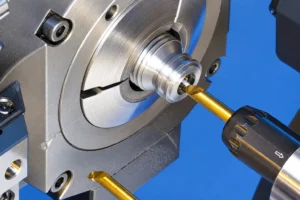
A long boring bar is typically required for a deep bore. The deeper the bore, the more susceptible the bar will be to deflection and vibration.
For instance, the bore of Ø20 mm and depth of 100 mm has a depth-to-diameter ratio of 5:1. This takes a longer tool reach than the 20 mm bore to a depth of 40 mm.
Do not exceed the functional requirement for depth of bore. Also consider boring-bar reach, chip removal, and coolant access during design for deeper holes.
Grooves and Threads
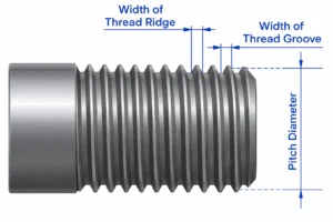
Grooves are an additional cutting operation. If the insert being used is not designed to cut the entire width of a groove, it may need to be cut in more than one pass.
Multiple passes are needed for threads as well. A longer toolpath or cut time will result from a long thread.
If it is a production part, ask yourself if the groove width, depth, length of the threads, and what kind of thread is needed for the assembly. Don’t increase the amount of thread for any reason unless there is more of it on the drawing.
Long Slender Parts
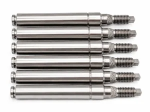
When turning a long, small-diameter part, it may bend. Subsequently, the setup may need a tailstock or steady rest, and cutting conditions may need to be lowered.
In one instance, a Ø 12 mm turning with an unsupported length of 150 mm is a problem, but in another, it is a short Ø 12 mm turning. This should then be read in conjunction with the planned workholding.
Reducing the unsupported length may make the part easier to machine if the part does not need to be long for the function.
Complex Profiles
More tool movement is needed for a profile that has a lot of diameters, tapers, radii, and small steps, and in most cases, it will need a separate finishing pass.
By using a simpler profile, toolpath length and machining operations can be reduced. For instance, if the part still has to perform a function, then several small-diameter steps can be merged into one diameter step without any extra cutting operations.
For production, examine the drawing and look for features that need to be added to the part but will not actually provide any function. These are typically the simplest ways to save cycle time.
CNC Turning Efficiency Problems and Practical Fixes
| Problem | Check First | Practical Fix |
| Roughing takes too long | Number of passes, DOC, feed | Increase DOC or feed within the insert and machine limits |
| Too many tool changes | Tool sequence | Use one tool for compatible features and remove unnecessary indexes |
| Long idle movement | Rapid and retract distance | Shorten X/Z movements while maintaining safe clearance |
| Loading takes too long | Chucking and part handling | Use a collet, bar feeder, or simpler loading method where suitable |
| Boring takes too long | Bore depth, bar reach, number of passes | Review bore depth and use a suitable boring bar |
| Threading takes too long | Thread length, pitch, number of passes | Use the insert manufacturer’s threading data |
| Cycle time changes during production | Insert wear, offsets | Set a defined insert-change point and limit manual offset changes |
CNC Turning Efficiency FAQs
What Is CNC Turning Cycle Time?
CNC turning cycle time is the time required to complete one part in the machine, including cutting, tool changes, programmed rapid movements, and other machine operations within the cycle.
Which CNC Turning Operation Usually Takes the Most Time?
Roughing often takes the largest share when the starting stock has a significant amount of material to remove. Deep boring, grooving, and threading can also add substantial time depending on the part geometry.
How Does Feed Rate Affect Turning Cycle Time?
A higher feed moves the tool through the cutting length faster. For example, increasing feed from 0.20 to 0.30 mm/rev reduces cutting time by one-third for the same RPM and cutting length, provided the tool and part can support the higher feed.
How Does Depth of Cut Affect CNC Turning Productivity?
A larger depth of cut removes more stock per pass and can reduce the number of roughing passes. The usable value is limited by the insert data, machine power, workholding, and part rigidity.
How Can CNC Lathe Tool Changes Be Reduced?
Look for the right sequence of tools and merge operations that require the same tool. Do not call the same tool more than once unless a feature sequence calls for it to be called more than once.
Does Bar Feeding Reduce CNC Turning Cycle Time?
If you are making blanks for bar work, you can save the time and trouble of loading each blank manually by using bar feeding. The saving is actually determined by loading time, part length, bar size, and production quantity.
How Can CNC Turning Cycle Time Be Measured Accurately?
Measure the real machine cycle time from cycle start to cycle end. If you’re searching for time savings, document the cutting time, tool changes, rapid movements, and part handling separately.
What Is a Good Way to Compare Two CNC Turning Programs?
Operate both programs from the same computer, using the same material, tooling, workholding, and part requirements. Compare cycle time, tool usage, surface finish, and finished part inspection results.
How Can Part Design Reduce Turning Cycle Time?
Remove features that are not required for the part’s function, reduce unnecessary profile changes, and avoid excessive bore depths, groove lengths, and thread lengths. Starting with stock close to the finished shape can also reduce roughing time.
CNC Turning Efficiency: Practical Takeaways
A useful starting point is the current cycle. Check cutting time, tool changes, rapid moves, loading, and unloading separately. This makes it easier to find the operation worth changing.
For example, if roughing takes up most of the cycle, look at the number of passes, feed rate, and depth of cut. If cutting time is already low, changing the feed may give little benefit compared with reducing tool changes or part handling.
Keep these points in the process review:
- Measure the current cycle.
- Find the longest operation.
- Check the cutting data for that operation.
- Remove unnecessary tool movements.
- Review tool changes and loading time.
- Check whether the part features are adding machining work.
- Measure the cycle after each change.
Trying to bring down the cycle time on a turned component? Send us the part drawing and current machining details. YD Rapid can review the turning sequence, stock size, tooling, and production quantity to identify practical changes that may shorten the cycle.