Key Takeaways
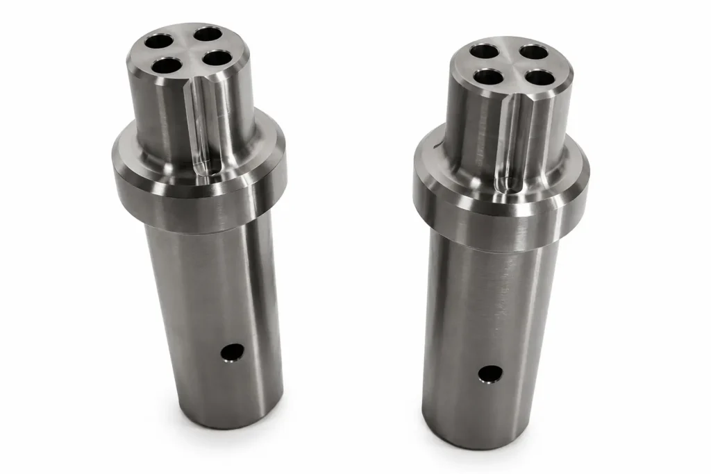
- CNC turning is mainly used for parts built around a rotating axis, such as shafts, pins, bushings, sleeves, and stepped components.
- The main drawing details for a turned part are usually the outside diameters, inside diameters, lengths, grooves, threads, chamfers, radii, and tolerances.
- A diameter tolerance controls how much the finished diameter can vary from its nominal size. This is especially important for shafts, bores, and mating features.
- Material affects the machining process. The specified material grade and condition should be confirmed before production rather than selecting a material based only on its general type.
- Features that are difficult to access with a turning tool, such as deep internal bores or narrow grooves, need to be checked during design.
- Tolerances and surface-finish requirements should be applied to the features that actually need them. They should not be tightened without a functional reason.
Introduction
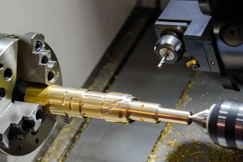
A CNC-turned part is usually recognized by its round features: a shaft with several diameters, a bushing with a bore, a threaded stud, or a sleeve with an internal and external diameter. During turning, the workpiece rotates, and the cutting tool machines these features to the dimensions shown on the drawing.
For a turned part, the important design questions are fairly practical. What diameters need to fit? How deep is the bore? Where is the thread? Which dimensions need tight tolerances? Can the tool reach the feature? What material and material condition are required?
These details affect how the part is manufactured and inspected. A diameter used as a bearing or mating surface may need tighter control than a non-critical outside diameter. Similarly, a deep bore or narrow groove may require more attention to tool access than a simple external diameter.
This guide covers the common features, tolerances, materials, and design considerations used for CNC-turned parts, with a focus on requirements that can be checked before sending a part for production.
What Are CNC Turned Parts?
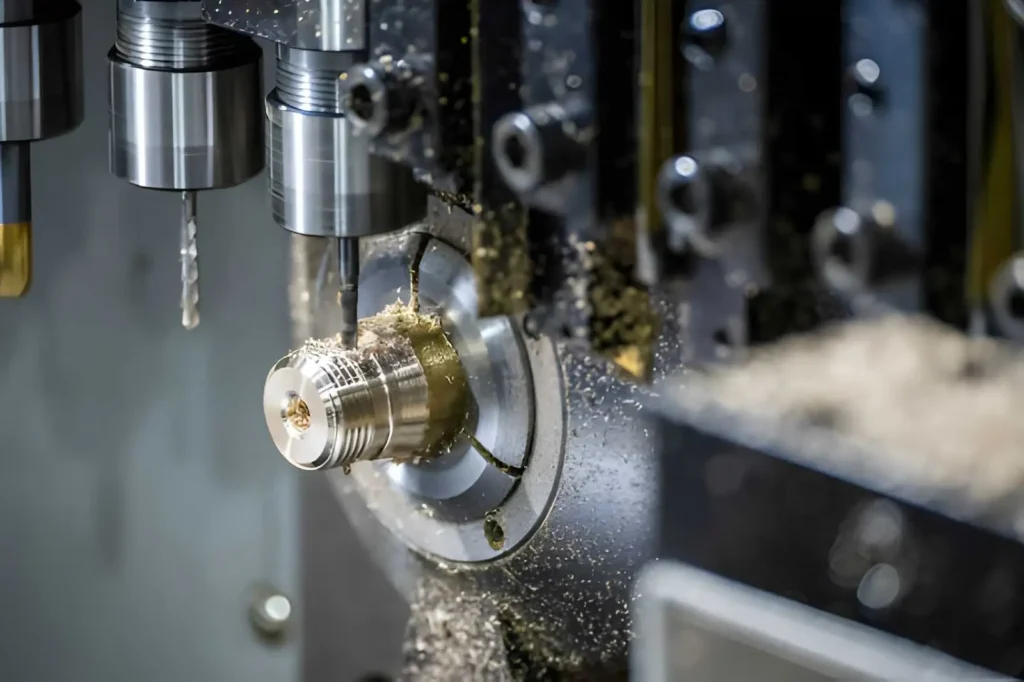
A CNC-turned part is made by rotating the workpiece around its center axis while a cutting tool removes material. In a typical CNC lathe, the workpiece rotates around the Z-axis, while the cutting tool moves mainly along the Z-axis and across the X-axis.These components are produced through CNC turning, where the workpiece rotates while a stationary cutting tool removes material.
For turning, the Z-axis controls the position along the length of the part, while the X-axis controls the diameter. Moving the tool toward the center reduces the diameter; moving it away from the center increases the diameter.
How CNC Turning Produces a Part
Here are the fundamental steps involved in CNC turning machining,
- Workpiece: spins about the Z-axis.
- Z-axis movement: moves the tool along the length of the part. The movement along the X-axis is used to adjust the tool diameter, as it moves towards or away from the centerline.
- External Turning: The material is taken off the outside diameter.
- Internal turning: A method of producing the inside of a hole or bore using a boring tool.
For instance, a drawing might specify a Ø30 mm section on the X-axis, which will determine the distance of the tool from the centerline to create the Ø30 mm section. If another section is Ø20 mm, then the tool will approach the center line to form the smaller diameter. Each section begins and ends on the Z-axis.
The drawing then gives the desired geometry, and the CNC program translates these dimensions into movements in the X- and Z-axis.
Parts Commonly Made by CNC Turning
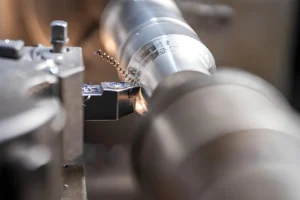
CNC turning is appropriate for parts having most of the essential features located around a central axis, such as:
- Shafts: Typically have multiple outside diameters and shoulders.
- Pins: Normally have 1 or more controlled diameters and lengths.
- Bushings: Need an outside diameter and an inner bore.
- Sleeves: Commonly have a cylindrical outside surface and a through bore.
- Threaded components: Can have internal or external threads.
- Stepped Cylindrical Parts: Parts that change in diameter along the Z-axis.
Common Features of CNC Turned Parts
A CNC-turned part may include several features in both the X and the Z axes. The drawing must indicate the size, location, and depth of each feature that will affect the finished part.
Outside Diameters and Steps
Outside diameters are machined on the outer surface of the rotating workpiece. A turned part can have several diameter sections along the Z-axis.
For instance, one portion might be 30 mm, and another might be 20 mm. The transition from one to the other forms a shoulder.
The drawing should contain definitions for:
- Outside diameter
- The length of each segment of a diameter
- Shoulder location
- Required radius or chamfer at transition area(s)
These dimensions give the radial size and location of each feature on the part.
Bores and Internal Diameters
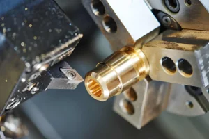
A bore is a cylindrical surface that is cut inside the part.
There are two common types:
- Through bore: runs through the part.
- Blind bore: ceases to bore at a specified depth.
If the drawing is a blind bore, it should include the diameter and length of the bore. The available depth should also be considered since the boring tool must reach the bottom of the feature.
A blind bore hole (with no hole end) of Ø20 mm × 40 mm, for instance, must have both the hole diameter and the hole length specified. The diameter is the size of the internal surface; the depth is how far the bore goes along the Z-axis.
Grooves and Relief Features
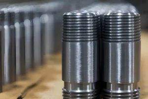
Grooves are cutouts in an outside or inside diameter. Common examples include:
- Outside Diameter Grooves: External grooves are on the outside diameter.
- A hole in the inside of a hole.
- Add relief grooves to the end of a threaded area
When the groove width, diameter, and location along the axis influence the part’s function, they should be specified.
Very narrow or deep grooves must be sufficiently wide to allow the cutting tool to enter and move out of the material around the groove. This is especially important when the groove is near a shoulder or in a bore.
Threads
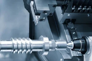
CNC turning can be used to create external threads as well as internal threads.
The thread callout should not just point to an area; it should point to the thread needed. According to the drawing, the standard may indicate:
- Thread size
- Pitch for internal threads and external threads
- The value of t is called TPI (threads per inch).
- Thread class/tolerance class.
- The thickness of the thread or the length of the threads.
For instance, M20 × 1.5 means the threads are a metric thread with a nominal diameter of 20mm and a pitch of 1.5mm. An inch thread callout, for example 1/4-20 UNC, specifies the nominal size (1/4 inch), 20 threads per inch, and UNC thread series.
Chamfers and Radii
Chamfers and radii help to define the shape of edges and the transitions between surfaces. Chamfer is used to remove a sharp edge at a certain angle or size. It can be attached to a shaft or hole to create an edge transition at the end of a shaft.
A transition between two outside surfaces is rounded with an external radius. The internal radius is the radius of the corner that is formed where two surfaces on the inside intersect.
When the size of these details is relevant to the assembly, clearance, sealing, tool access, or final geometry, they will need to be included on the drawing.
Tapers and Contoured Profiles
A taper changes the diameter gradually along the Z-axis rather than producing a constant cylindrical surface. A curved or profiled surface could also be a turned part. The drawing must include sufficient information to establish the desired profile—including diameters, lengths, angles, radii, or dimensions of the profile.
The geometry in a simple taper can be defined by an angle or by the two end diameters and the distance along the axis. For more complex profiles, they may need more dimensions or a specified profile tolerance, which will allow the shape to be checked after manufacturing.
CNC Turning Tolerances
A turned part does not have to be machined to one exact number. The drawing gives a target size and an allowed variation. The machinist uses that information to set up the operation, and inspection checks the finished feature against the stated limits.
What a Diameter Tolerance Controls
For example, if an engineer draws a shaft with an outside diameter of 20.00 ±0.02mm, the drawing is considered a model. The acceptable finished size is 19.98- 20.02 mm. A measured diameter of 20.01 mm is acceptable; 19.96 mm is not.
In the case of a shaft that is inserted into a bearing or bore, this is directly related to the fit. Size requirements for the mating bore are also important and must be considered along with the size of the fitting.
Dimensional Tolerances for Length and Steps
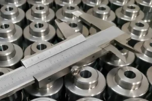
The dimensions on a turned part indicate where features are. A drawing can specify the following:
- Overall length
- The distance between the end face and the shoulder.
- The reduced-diameter portion’s length.The length of the reduced diameter section.
- Groove position
- Threaded length
What effect does that dimension have on the assembly is important. The distance from the reference face to a shoulder that provides a bearing may require a controlled tolerance. Where a section only provides a clearance level, the same control level may not be required.
Tolerances for Mating Features
Mating is recommended to be carried out with a checkup of mating features. If a Ø20 mm shaft is inserted into a bore of the same size, or is slightly smaller, the actual sizes of both components will dictate whether the shaft slides into the bore, fits tightly, or must be pushed into the bore.
The same goes for:
- Bearing seats
- Press-fit diameters
- Locating diameters
- Sliding shafts
The drawing shall indicate tolerances necessary to obtain the required fit in addition to nominal dimensions for these features.
Surface Finish Requirements
Surface finish is not necessarily a requirement of dimensional tolerance. The surface may be fine for a seal, bearing, or sliding contact, but the diameter may not be.
On a drawing, indicate the surface finish required if the surface has a functional contact requirement. The general finish requirements listed are applicable to other surfaces.
Avoiding Unnecessary Tight Tolerances
A close tolerance is always linked to a certain requirement. If an extra-small tolerance is desirable, it may be less useful to allow a non-mating diameter to vary by a reasonable amount. It provides only one new limit for production and inspection.
It would be more appropriate to designate the dimensions that will determine fit, bearing location, sealing, movement, or assembly position and to provide the necessary tolerance for that dimension. General tolerances may be used for the other dimensions.
Materials for CNC Turned Parts
The first step in material selection is the part itself. It is important that the material callout on the drawing specifies exactly what grade and condition the material must be produced in. So the manufacturer now has a clear material specification to work on.Material selection should consider strength, corrosion resistance, machinability, operating temperature, and cost. See the available CNC machining materials for metal and plastic parts.
Common Metal Materials
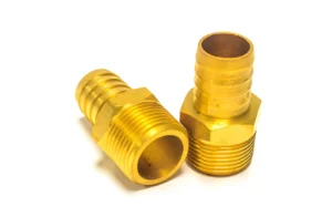
CNC Turning can be applied to many engineering metals, such as:
- Aluminum alloys
- Stainless steels
- The steels used to make the castings are carbon or alloy steels.
- Brass and copper alloys
- Titanium alloys
Material name is not always sufficient for production. The drawing statement “aluminum” or “stainless steel” does not specify the grade. When the grade has an influence on the properties or the manufacturing of the part, the required alloy shall be indicated.
Material Grade and Condition
The grade may refer to the product, and the condition may refer to the way the product has been supplied or treated.
The information that needs to be included in a drawing can include:
- Alloy or steel grade
- Aluminum temper
- Heat-treatment condition
- Required hardness
- The annealed/ hardened condition.
Material Selection Based on Part Requirements
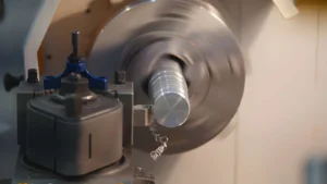
See what the completed object needs to do before deciding on the material. When talking about a turned piece, these are the questions that could be asked:
- Does it have a mechanical load?
- Will it be wet or in contact with chemicals?
- Will another part rotate or slide against it?
- Does the part need to remain lightweight?
- Is there a higher temperature limit for its operation?
- Do the parts need to be surface-treated (heat-treated or otherwise)?
These requirements further restrict the grade of materials that can be used. The material should be selected based on the required properties and service conditions, and not just the easiest to machine.
Material and Machinability
The material used for a part also becomes a requirement for the machining. The cutting behavior, tool wear, surface finish, and planning of the turning operation can be influenced by the grade and condition.
That is why it is important to verify material prior to machining. Where the requirement is to use a particular alloy/condition, the supplied material should be checked against this requirement rather than be replaced with another grade of the same general alloy or condition.
CNC Turned Part Design Guidelines
Before sending a turned part for machining, check the geometry from the tool’s point of view. The main question is not simply whether the machine can make the shape, but whether the cutting tool can reach each feature without an unnecessary setup or special operation.
Keep the Main Geometry Suitable for Turning
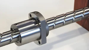
A simple turned part should be built mainly from features around the X/Z coordinate system:
- Outside diameters
- Steps and shoulders
- Bores
- Grooves
- Threads
- Tapers
If the drawing also contains a cross-hole, flat, slot, keyway, or radial hole, identify it as a separate feature. These features are not produced by ordinary straight turning and may require live tooling or another machining operation.
Design Diameters and Lengths With the Process in Mind
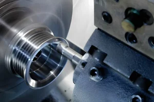
Check the diameter-to-length relationship before finalizing a long shaft section. For instance, a long Ø10 mm piece is more sensitive to bending than a short Ø10 mm piece. If the length is not required for the functionality of the part, then a shorter feature will be easier to machine.
Look up at the location of each diameter on adjacent shoulders, too. There has to be sufficient clearance for a tool to get near the cutting area and out of the area.
Consider Tool Access for Grooves and Shoulders
Don’t consider only the size of the grooves. Determine if the cutting tool will fit in the space. This is particularly true if the drawing has:
- Narrow external grooves
- Deep grooves
- Closely spaced shoulders
- Internal grooves
- A channel close to another feature.
If you have a groove at the bottom of a shoulder, you should make sure that the tool has ample space to get to the bottom without striking the adjacent face.
Design Internal Bores Carefully
For a bore, diameter and depth should be considered together. A Ø10 mm bore that is 15 mm deep is a different machining requirement from a Ø10 mm bore that is 100 mm deep. As the bore becomes deeper relative to its diameter, tool access and rigidity become more important.
For blind bores, also define the required depth and bottom geometry. If the bottom does not need to be square or fully flat, the drawing should not imply a tighter geometry than the part requires.
Use Practical Internal Corner Radii
An internal corner produced by turning normally has some radius because the cutting tool has a defined nose geometry.
If a drawing shows a sharp internal corner, check whether that corner is actually required for assembly. If not, allowing a small radius can make the feature easier to produce.
Where a mating component must seat against that corner, specify the required radius or relief so the two parts do not interfere.
Provide Thread Relief Where Required
When a thread finishes against a shoulder, the tool needs somewhere to complete its cutting path. A thread relief groove provides that space. This is useful when the threaded section must extend close to a shoulder, and the thread has to be fully formed to the specified length.
The relief should be sized according to the thread and the functional requirement rather than added as a generic groove to every threaded feature.
Avoid Unnecessary Geometry
Look at each feature and its intended purpose. A second step, decorative groove, extra chamfer, or complex profile that has no effect on fit, clearance, movement, sealing, or appearance may not need to be on the part.
Simplifying these features can reduce the number of turning operations and make the drawing easier to manufacture and inspect.
Drawing Requirements for CNC Turned Parts
A turning drawing should leave the supplier with enough information to make the part without having to guess the material, finished sizes, thread details, or inspection requirements. The drawing should define the finished part; the machining method does not need to be written out unless a particular process is required.
Material and Material Condition
Write the material grade on the drawing. For example, aluminum is not a complete specification of a material unless a specific alloy is specified. If the grade and temper are specified in the requirement, the drawing shall specify the required grade, e.g., 6061-T6.
The same applies to steel. If a part is required in a specific heat-treated condition, indicate the material and condition per the part, not leave it up to the supplier.
If applicable, also explain:
- Required hardness
- Heat-treatment condition
- Aluminum temper
The standard to which specific materials are designated.Standard to which materials are designated.
Dimensions and Tolerances
The drawing should be sized to provide the actual dimensions to make and check the part. For a turned product, this normally consists of:
- Outside diameters
- Bore diameters
- Overall length
- Shoulder locations
- The width and diameter of the grooves.
- Threaded length
- Chamfers and radii
Avoid using the geometry of the CAD model to convey a critical size, unless it has to be controlled. For instance, if the diameter of the bearing seat is Ø25 mm, the required diameter tolerance is given to it. If there is a shoulder controlling the location of that bearing, apply the same tolerance to the face-to-shoulder measurement.
A general tolerance applies to ordinary dimensions, and critical dimensions can have their own limits.
Thread Callouts
A note saying “M12 thread” does not contain all the information needed in many cases. A complete callout should identify the required thread standard and size, along with the details needed for production and inspection.
For example:
- M12 × 1.75: metric size and pitch
- M12 × 1.75-6H: adds the internal thread tolerance class
- 1/4-20 UNC-2B: identifies an inch thread, thread series, and internal thread class
For a blind hole, show the required thread depth. If the hole itself needs to be deeper than the threaded portion, show the hole depth separately.
Surface Finish
Only call out a specific surface finish where the surface actually has a requirement. A bearing seat, sealing diameter, or sliding surface may need a controlled finish. A surface that has no contact or functional requirement may not need the same value.
Keep the surface-finish symbol or note attached to the specific surface it applies to. This avoids making the supplier apply a finish requirement to surfaces that do not need it.
Additional Manufacturing Requirements
Some requirements do not describe the basic turned geometry but still need to be included in the drawing.
For example:
- Heat treatment: state the required hardness or treatment condition.
- Plating/coating: identify the required finish and specification where applicable.
- Deburring: state the required edge condition if it is not covered by a general note.
- Inspection: identify any dimensions or characteristics requiring specific inspection.
- Documentation: state whether material certificates, inspection reports, or other quality records are required.
The main rule is simple: if a requirement affects the finished part and the supplier needs it to manufacture or inspect the part, put it on the drawing or in the controlled manufacturing specification. Don’t leave a critical requirement only in an informal message or verbal instruction.
CNC Turned Parts FAQs
What Parts Are Suitable for CNC Turning?
Parts with a mainly round shape are a good fit for CNC turning. Common examples are shafts, pins, bushings, sleeves, spacers, and threaded parts.
What Are the Most Common Features on a CNC-Turned Part?
You will commonly see outside diameters, steps, shoulders, bores, grooves, threads, chamfers, radii, and tapers. These features are defined by their dimensions and locations on the drawing.
What Tolerances Can CNC Turning Achieve?
There is no single tolerance that applies to every turned part. The result depends on the machine, material, part size, feature geometry, and tolerance being specified. A bearing seat, for example, may need tighter control than a non-functional diameter.
Which Materials Can Be CNC Turned?
Common materials include aluminum alloys, stainless steel, carbon and alloy steels, brass, copper alloys, and titanium. The drawing should give the exact grade when the material specification matters to the part.
How Should Threads Be Specified on a Turned Part Drawing?
Give the thread size and pitch or TPI, along with the thread series and class where required. The drawing should also show the threaded length or depth. A blind threaded hole should have the thread depth clearly defined.
How Should Internal Bores Be Designed?
Give the bore diameter and depth, and show whether it is a through or blind bore. A small bore with a large depth also needs to be checked for tool access before the geometry is finalized.
Why Are Internal Corner Radii Used on Turned Parts?
A turning tool cannot normally produce a perfectly sharp internal corner. A small radius gives the tool room to cut the corner. If a mating part needs a particular corner shape, that radius should be shown on the drawing.
What Should Be Included on a CNC Turning Drawing?
At a minimum, the supplier needs the material, finished dimensions, tolerances, thread details, and required surface finish. Add heat treatment, coating, inspection, or other requirements when they apply to the finished part.
How Can I Make a Turned Part Easier to Manufacture?
Look at the drawing from the tool’s position. Deep small bores, very narrow grooves, difficult internal corners, and unnecessarily tight tolerances can make a part harder to produce. If those features are not required for the part to work, simplify them.
Can a CNC-turned part include milled features?
A turned part can also have flats, slots, cross-holes, keyways, or other milled features. These features need additional tool movement, such as live tooling on a turning center, or may require a second machining operation.
Conclusion
A CNC-turned part should be designed around the way its diameters, bores, grooves, threads, and shoulders will actually be machined. The material and its condition also need to match the part’s working requirements, while tolerances should be set according to the required fit and function.YD Rapid provides CNC machining services for custom turned parts, from prototypes to repeat production based on customer drawings.
Before sending the part for production, check the drawing for the material grade, dimensions, tolerances, thread specifications, surface finish, and any heat-treatment or coating requirements. Also check features such as deep bores, narrow grooves, and internal corners for tool access.
A clear drawing and practical tolerances give the manufacturer a defined target for machining and inspection and can help avoid unnecessary changes during production.
Have a CNC-turned part ready for production? Send your CAD model and drawing to YD Rapid for a DFM review, material guidance, and CNC machining quotation.