Key Takeaways
- CNC milling and CNC turning remove material in different ways and are designed for different part geometries.
- In milling, the cutting tool rotates while moving along the X, Y, and Z axes to machine flat surfaces, pockets, slots, and complex profiles.
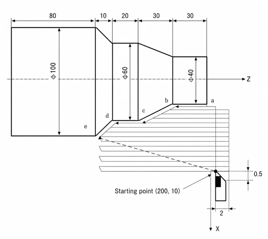
- In turning, the workpiece rotates while the cutting tool feeds mainly along the X and Z axes to produce cylindrical and rotational features.
- Part geometry is usually the first factor in deciding whether milling or turning is the better manufacturing process.
- Both processes can achieve high dimensional accuracy, although the achievable tolerance depends on the feature, material, and machining setup.
- Many precision components combine CNC turning and milling to complete multiple features without moving the part between different machines.
Introduction
A CNC part rarely starts with the question, “Should it be milled or turned?” Instead, the drawing usually provides the answer. A shaft with multiple diameters naturally follows a turning process, while a mounting plate with pockets and drilled holes requires milling. Some components even combine both, using turning to create the main shape and milling to add flats, slots, keyways, or threaded features.
Although both processes remove material, they follow different machining principles. CNC milling moves a rotating cutting tool along multiple axes to create a wide range of shapes, whereas CNC turning rotates the workpiece while the cutting tool removes material from its outer or inner diameter. Understanding these differences before production helps simplify machining, reduce unnecessary operations, and select the process that best matches the part design.
In this article, you’ll learn how CNC milling and CNC turning differ in machine movement, cutting tools, part geometry, achievable tolerances, production cost, and the types of components each process is designed to manufacture.
How CNC Milling Works
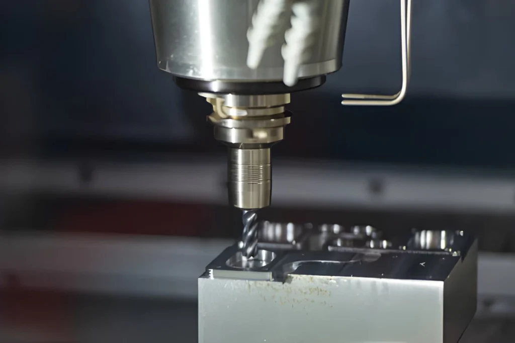
In CNC milling, a rotating cutting tool removes material from a stationary workpiece to create flat surfaces, slots, pockets, holes, and complex contours.
A CNC milling machine shapes the parts by machining one feature at a time. The programmer doesn’t treat the part as a single operation. Instead, each surface, pocket, slot, and profile follows its own machining sequence until the drawing is complete.
The cutter changes automatically throughout the program, allowing several machining operations to be completed before the part is removed from the machine.
Material Removal During Milling
Usually, shops start with a larger cutter for removing excess stock, since it can remove material faster. Once the major shape has been cut, smaller cutters are used to make details that are not possible to machine with the larger cutter.
Take an example of a machined aluminum housing. The surface can be initially cleaned with a 63 mm indexable face mill. The internal pockets are then opened with a 12 mm carbide end mill, and the internal corners and narrow features are completed with a 6 mm end mill.
Drilling and tapping have been done before the final deburring operation if threaded holes are part of the design. The same time-critical operation is used for stainless steel, brass, titanium, and engineering plastics; only the geometry of the cutter, spindle speed, and feed rate are changed based on the material being machined.
Machine Axes Used in CNC Milling
The ease with which various faces of a part can be accessed is largely determined by the number of machine axes.
3-Axis CNC Milling
The spindle is moved in the X, Y, and Z directions by a 3-axis machining center. It is the most common option for parts that can be processed on one side of the material, such as base plates, brackets, covers, fixtures, heat sinks, and electronic enclosures.
Most general machining operations are performed on 3-axis machines since they offer good accuracy and are easy to program.
4-Axis CNC Milling
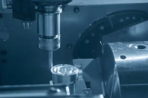
A 4-axis machine has an additional A axis, which is used to rotate the workpiece around the X axis. The rotary table rotates the component between positions so that a different side of the component can be accessed without the need to unclamp it to machine the other side.
It is often used for valve bodies, manifolds, indexed fixtures, and parts to be machined on multiple faces.
5-Axis CNC Milling
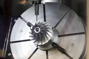
A 5-axis machining center is a combination of the other 3 linear axes with 2 rotary axes, usually A and C or B and C. No need to repeat setups because the spindle can come to the work at various angles. This enables the production of parts such as impellers, turbine blades, aerospace brackets, orthopedic implants, mold inserts, and other deep hole or complex surface parts.
Common Milling Operations
Each of these operations is for a specific purpose, and the cutter is different throughout the machining process.
Face Milling
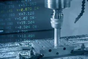
The stock is sometimes face milled for a flat reference surface prior to the small features being machined. Face mills with carbide inserts that can be mounted on an indexer are popular since they cut material in a large area.
End Milling
Square end mills are used for most machining applications. These cutters create shoulders, side walls, steps, and flat bottoms. Depending on the material and quantity of production, they can be found in solid carbide, high-speed steel, and indexable.
Slot Milling
Slots are typically cut with centre-cut end mills that are the desired width of the slot. Bigger slots can be roughed with a smaller cutter, before a final pass closes them to size.
Pocket Milling
Unlike cutting the pocket depth at once, the pockets are cut in stages. Modern CAM software creates adaptive toolpaths, which keep the same cutter load as the cavity is being cleared.
Profile Milling
The shape on the outside is typically the last shape to be machined. Square end mills are ideal for straight profiles, while ball nose end mills are suitable for molds and aerospace parts that have blended surfaces, radii, and 3D contours.
Types of Materials a CNC Milling Machine Can Cut and Shape
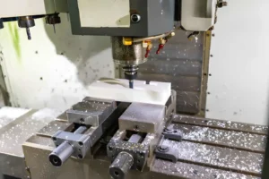
The same machining process can be used to produce parts for various industries, with the same machine and tooling, and applies to both metals and engineering plastics.
Typical materials that are commonly machined include: 6061 and 7075 aluminium, 17-4 PH stainless steel, 304 stainless steel, 316 stainless steel, carbon steel, alloy steel, brass, copper and Grade 5 titanium.
Commonly used engineering plastics are POM (Delrin), ABS, Nylon (PA6), Polycarbonate (PC), PEEK, PTFE, UHMW-PE, HDPE and PVC. The cutting parameters are different for each material, while the machining process itself is the same.
Parts commonly made by CNC Milling
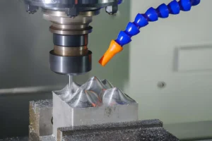
Generally, milling is chosen when a part has a combination of feature types. The hydraulic manifold can have many drilled passages, holes, sealing faces, and mounting surfaces. A robotic bracket can integrate pockets, slots, counterbores, and precision mounting faces all in one bracket.
In the same way, mold bases, fixture plates, medical instrument parts, heat sinks, gearbox housings, and electronic enclosures are treated. In the latter two cases, the same manufacturing method can be used for different geometries.
How CNC Turning Works
In CNC turning, the workpiece rotates while a cutting tool removes material, making the process suitable for shafts, bushings, pins, and other cylindrical parts.
Unlike milling, turning begins with round stock. The material is held in the chuck and rotates while different cutting tools gradually form the required diameters and features. As the program progresses, the outside profile, internal bore, grooves, threads, and finished length are machined in sequence. Many turned parts leave the machine finished because several operations can be completed in one setup.
Material Removal During Turning
The sequence of machining will depend on the drawing, but most turned parts will be machined in a similar sequence. The first cut will make a good reference face and help to control the other dimensions. After that, the outside diameter is machined before it is assembled to grooves, bores, chamfers, and threads, etc.
A selection of different insert geometries is selected throughout the development of the part. A roughing insert cuts off the bulk of material, and a finishing insert cuts the final diameter and finish. When an internal bore is shown in the drawing, it is completed by a boring bar before the part is removed from the rest of the bar stock.
Machine Axes Used in CNC Turning
The machine configuration determines the types of products that can be made without removing the part from the spindle.
2-Axis Turning
In most cases, CNC lathes have X and Z axes. The X axis will adjust the part’s diameter, and the Z axis will adjust the part’s length. This is for use on a substantial proportion of shafts, pins, sleeves, bushings, rollers, and threaded parts for general manufacturing.
Turning Centers with Live Tooling
Some CNC lathes have powered tools which spin freely off the spindle. This allows for drilling holes, milling flats, keyways, or simple milled features to be performed after turning. The part remains in the same set-up for the most part, and extra alignment is not needed.
Multi-Axis Turning Centers
Y-axis, C-axis, and sub-spindle machines deal with parts that have features on multiple sides. It is useful in hydraulic fittings, medical connectors, aerospace parts, and precision valve parts where both ends of the component are processed in the same process.
Common Turning Operations
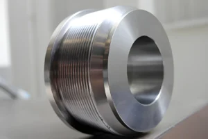
Each operation adds a different feature to the component rather than repeating the same cutting process.
- Facing creates a flat reference surface before the remaining dimensions are machined.
- Straight Turning reduces the outside diameter and creates shoulders or stepped sections throughout the length of the part.
- Grooving cuts are used to create narrow channels to hold rings, seals, or assembly features with defined width and depth.
- Parting allows for separating the finished part from the leftover bar stock. It can perform external and/or internal thread turning directly from drawing specifications, with suitability for custom size and pitch turning.
- Boring expands a hole that has already been bored to get a better tolerance in diameter and make a smoother inner surface for bearings, bushings, or precision fits.
Parts Commonly Made by Turning
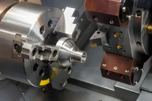
When the drawing is based on diameters, instead of flat surfaces, turning is often the first machining process that is thought about.
These include drive shafts, bearing sleeves, spacers, bushings, rollers, threaded adapters, hydraulic fittings, valve stems, pins, couplings, and sensor housings.
Many of these are finished on a CNC turning center; some of them later go to a milling machine for further work.
Which Part Shapes Are Better for Milling or Turning?
The drawing usually points to the machining process long before production begins. Flat features, outside diameters, internal cavities, and mounting faces each suggest a different machining approach. Reading the complete geometry first gives a clearer picture of the manufacturing route.
Flat and Prismatic Components
Brackets, fixture plates, mold bases, electronic enclosures, and manifolds are manufactured with flat surfaces instead of an outside diameter. Pockets, slots, threaded holes, and faces for mounting on multiple sides are common features on these parts.
The basic manufacturing process remains unchanged while the workpiece is being produced; the CNC milling machine can process each feature without changing the production process, which makes the production process straightforward.
Shafts and Cylindrical Parts
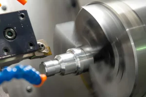
Bushings, bushed round bar, rollers, spacers, valve stems, and bearing sleeves are first manufactured in round bar stock. The key dimensions of their main features are set by the outside diameters, shoulders, grooves, and internal bores all on the same centerline. This geometry is a natural product of a CNC lathe, which creates each diameter consecutively from one setup.
Complex Multi-Face Components
A few drawings contain features on multiple faces of the same part. The cutting tool must move towards the part in various directions, such as angled holes, deep pockets, inclined surfaces, and blended contours.
With four-axis and five-axis machining, repeated repositioning is eliminated, and these features are held true while they are being produced.
Parts That Need Both Processes
Numerous production components have a combination of rotational and prismatic elements. A motor shaft can have bearing journals, a milled keyway, cross-drilled holes, and threaded ends. A turning center could set up a hydraulic connector with a plan to take it to the milling machine for wrench flats and mounting parts.
Generally, the machining plan will be simpler when reviewing the entire part instead of its individual features.
CNC Milling vs Turning at a Glance
Both processes remove material, although they create different types of components. In most cases, the part geometry determines the machining process.
Flat and multi-sided parts are generally milled, while cylindrical components are produced on CNC lathes. Reviewing the drawing before machining makes it easier to select the most suitable process and avoid unnecessary operations.
| Feature | CNC Milling | CNC Turning |
| Material Movement | The workpiece remains fixed while the cutter removes material from different directions. | The workpiece rotates while the cutting tool removes material from the outside or inside diameter. |
| Tool Movement | Rotating cutter moves along programmed X, Y, and Z toolpaths. | Single-point cutting tool feeds mainly along the X and Z axes while the workpiece rotates. |
| Primary Machine Axes | 3-axis (X, Y, Z), with optional 4th and 5th rotary axes for complex machining. | Primarily X and Z axes; live-tool lathes may also include Y-axis and C-axis for milling operations. |
| Best Part Shape | Prismatic, flat, multi-face, and irregular components. | Cylindrical, conical, tubular, and rotationally symmetric components. |
| Typical Features | Flat faces, pockets, slots, steps, contours, keyways, drilled and threaded holes. | Shafts, shoulders, grooves, tapers, threads, bores, and external or internal diameters. |
| Common Materials | Aluminum, stainless steel, carbon steel, brass, copper, titanium, engineering plastics. | Aluminum, stainless steel, alloy steel, brass, titanium, copper, engineering plastics. |
| Typical Dimensional Accuracy | Generally ±0.02 to ±0.05 mm for standard CNC machining; tighter tolerances are achievable for critical features. | Generally ±0.01 to ±0.03 mm for turned diameters under stable machining conditions. |
| Typical Surface Finish | Approximately Ra 0.8 to 3.2 μm, depending on cutter, toolpath, and finishing passes. | Approximately Ra 0.4–1.6 μm on finished diameters using appropriate cutting parameters. |
| Production Speed | Well suited for parts with multiple faces and complex geometries, although cycle time increases as feature complexity grows. | Highly productive for rotational parts because several diameter features can be machined in a single setup. |
| Material Utilization | Usually starts from blocks, plates, or billets, with more material removed to create the final shape. | Commonly starts from round bar stock, allowing efficient machining of cylindrical components. |
| Typical Part Examples | Mounting plates, brackets, molds, housings, fixtures, manifolds, heat sinks. | Shafts, pins, bushings, rollers, spacers, couplings, threaded connectors. |
Cost Comparison Between Milling and Turning
Looking at the hourly machining rate alone rarely tells the full story. The final price comes from several factors working together, including:
- Machining sequence
- Cutting tools
- Setup time
- Production quantity
Two parts made from the same stainless steel can receive very different quotations simply because their geometry requires a different manufacturing approach.
Material Removal Time
Material removal has a direct impact on machine time, particularly when machining from solid stock. The drawing is not complete until the aluminum prismatic housing is rough, semi-finished, and finished. The stepped shaft is easier to machine as the cutting tool is always on the same centerline during most of the process.
The general range of roughing rates from tooling manufacturers is 50-300 cm³/min for CNC milling and 100-500 cm³/min for CNC turning; however, this varies depending on the cutter size, spindle power, material of the workpiece, and cutting parameters.
Machine time is typically quoted at $60-150 per hour for standard 3-axis milling machines, and $80-200+ per hour for CNC turning centers or multi-axis machines (depending on region and machine capabilities), so longer machining cycles can be noticeable on the final quotation.
Machine Setup
Each new setup requires preparation before the first part can be machined. A standard shaft can be chucked once, while a manifold or mounting bracket can be chucked multiple times to position different faces.
Typically, setup time is 30 minutes to 2 hours of shop time for prototype work. The cost of setup can be as high as US$30 to US$300 (at US$60-150 per hour) before any parts are made. This cost is spread over more parts in larger production batches, and thus has less influence on the price of the parts.
Tooling Costs
The tooling cost does not only apply to the cutter itself. During production, all insert, tool changes, and special cutters are added.
A normal carbide turning insert ranges in cost from US$8-20, and premium grades suitable for stainless steel, titanium, and high-temperature alloys can be as high as US$20-40 apiece.
Solid carbide end mills for CNC milling usually cost between $20 and $150, depending on the diameter, coating, and cutting length of the end mill.
The larger indexable face mills are more expensive initially, but only the inserts need to be changed during normal production.
For higher numbers of pockets, profiles, threads, and drilled features, more cutting tools are added to the program, further adding to the tooling cost for extended production runs.
Production Volume
Prototype pricing covers programming, setup, and verification of the process before start-up. Those activities stay almost identical irrespective of the part or ten parts that are produced.
After 100-500 units are produced, manufacturers tend to fine-tune fixtures, tool paths, and cutting parameters to reduce cycle time. During larger production runs, automated bar feeders on CNC lathes, pallet changers on machining centers, and robotic loading systems further cut down on labor cost.
Table: Milling vs Turning Cost Comparison
| Cost Factor | CNC Milling | CNC Turning |
| Typical machine shop rate* | US$60-150/hour (3-axis), US$100-250+/hour (5-axis) | US$80-200+/hour (2-axis to multi-axis turning centers) |
| Typical setup time | 30 minutes-2 hours | 20 minutes-1.5 hours |
| Typical roughing removal rate | 50-300 cm³/min | 100-500 cm³/min |
| Typical cutting tools | Face mills, end mills, drills, thread mills, ball nose cutters | Turning inserts, boring bars, grooving tools, threading inserts |
| Typical tool cost | Solid carbide end mills US$20-150 | Carbide inserts US$8-40 each |
| Material utilization | Lower for billet machining with extensive stock removal | Higher when bar diameter closely matches the finished part |
| Best production range | Prototypes, custom parts, complex geometries | Medium- to high-volume rotational components |
Can One Part Use Both Milling and Turning?
Many production drawings contain features that belong to different machining processes. It is common to see a part with precision outside diameters, internal bores, wrench flats, threaded holes, and cross holes on the same drawing. Rather than changing the design to suit one machine, manufacturers normally plan the machining sequence around the features that need to be produced.
Turn-Mill Manufacturing
Typically, the first operation forms the features that define the part geometry. These are the diameters of the bearings and shoulders of a shaft.
After all dimensions are made, any additional features like keyways, wrench flats, oil holes, or drive slots are milled. All the drawing remains the same; only the work process is different for different features.
Multi-Operation CNC Machines
With some components, there is no need to move them from the turning center until they are finished. This is possible with live tooling, which extends the turning cycle with drilling and milling. This is a popular method for hydraulic fittings, threaded connections, valve parts, etc. because several features can be completed prior to unloading the part.
Benefits of One Setup
Transporting a part between two machines also means finding the part twice. If it is necessary to keep the features close to the turned diameters, one setup is much easier to inspect. Hole positions, milled flats, and turned surfaces are all marked on the same machining position, rather than being set up again on another machine.
Design Tips Before CNC Machining
Production problems are often easier to solve on the drawing than on the machine. A quick design review before machining usually removes unnecessary operations and simplifies manufacturing.
Match the Design to the Process
Start by sketching the general shape of the part. Flat faces, pockets, and profiles are best suited to milling; cylindrical parts to turning.
When the route of the machine operation is carefully planned, it is often possible to save an additional operation later in the process.
Reduce Unnecessary Features
Each additional feature adds part of the machining process. Check for grooves, pockets, chamfers, and threads to make sure they are needed before drawing them.
Consider Tool Access
Hard-to-reach features may need smaller cutters, longer tools, or extra setups. Making a few simple adjustments, like a change of an inside corner radius or a change to a wider pocket, can help make machining a breeze.
Apply Practical Tolerances
Reduce tolerances for aspects that regulate assembly, bearing fits, sealing surfaces, or alignment. Typical dimensions usually can be used with standard machining tolerances, which do not impact the performance of the part.
Typical Applications of Milling and Turning
Many components combine milling and turning because each process creates different features on the same drawing.
Aerospace Components
Large milled pockets with turned bearing seats and precision bores are often combined in aircraft brackets, actuator parts, and structural fittings to achieve dimensional precision and weight savings.
Automotive Shafts and Housings
Common parts turned and milled are transmission shafts, wheel hubs, gearbox housings and steering components. Outside diameters are first machined,d and then bolt patterns, keyways or mounting faces are machined.
Medical Components
Fine threads, precision diameters and smooth machined surfaces are found on bone screws, surgical instruments and medical connectors. Material certification and inspection records are also a key focus of production.
Robotics and Automation
Servo housings, drive shafts, couplings, and end-effectors are a mix of rotational components and holes and machined faces. These mixed geometries are not a single process, and the machining sequence is planned around these.
Industrial Equipment
A wide variety of geometries are used with hydraulic manifolds, rollers, spacers, valve parts, and bearing supports. Some parts are completely machined on a machining center; others are first machined on a lathe before secondary milling is performed.
Choosing a CNC Machining Supplier
Before placing an order, spend a few minutes reviewing what the supplier can actually do. The machine list is only one part of the picture. Engineering support, inspection capability, and production experience often have a much bigger impact on the finished part.
Engineering Support
Ask whether the CAD model and drawing are reviewed before machining starts. This discussion usually covers the machining sequence, material selection, critical dimensions, and any features that may need adjustment before production.
Milling and Turning Capability
Look at the part instead of the machine list. If the drawing combines shafts, flats, drilled holes, pockets, and threaded features, confirm that the supplier can complete the entire part instead of outsourcing part of the work.
Inspection Equipment
The inspection process should match the drawing. A supplier should be able to explain how critical diameters, hole positions, and geometric dimensions will be checked before the parts are shipped.
Prototype to Production Capacity
A prototype is only the beginning. If larger quantities are planned, ask whether the same machining process, inspection method, and material can be maintained throughout production.
Supplier Checklist
| Review Item | Recommendation |
| DFM review | ✓ |
| CNC milling | ✓ |
| CNC turning | ✓ |
| 3-axis machining | ✓ |
| 5-axis machining | ✓ |
| CNC lathes | ✓ |
| CMM inspection | ✓ |
| Material certification | ✓ |
| Prototype support | ✓ |
| Production support | ✓ |
CNC Milling and Turning Services at YD Rapid
Every part starts with a drawing, and selecting the right machining process is part of achieving the required result. At YD Rapid, our engineering team reviews your CAD files before production to confirm the most suitable machining approach, identify potential manufacturing issues, and provide free DFM feedback whenever improvements are possible.
As an ISO-certified manufacturer, we provide both CNC milling and CNC turning for metals and engineering plastics, supporting everything from simple machined components to complex multi-process parts. Whether you need a single prototype or full production, our team focuses on consistent machining, dimensional inspection, and fast project turnaround.

Upload your CAD files today to receive a fast quotation, engineering review, and manufacturing support from prototype to production.
FAQs
Is CNC milling more accurate than CNC turning?
Accuracy depends on the feature being machined rather than the process itself. Milling is well suited to flat surfaces, pockets, and profiles, while turning provides excellent accuracy for diameters, shoulders, and concentric features.
Can a turned part also be milled?
Many production parts include both turning and milling. A component may be turned to create its main diameters before milling is used to add flats, keyways, cross holes, or threaded features.
Which process is better for shafts?
Shafts are generally produced by CNC turning because the main features are based on outside diameters and a common centerline. Additional features such as keyways or cross holes are often added by milling after turning.
Why do some parts require both milling and turning?
Some drawings combine cylindrical features with flat faces, slots, holes, or pockets. Using both machining processes allows each feature to be produced with the most appropriate method without changing the part design.
Is CNC turning faster than milling?
For parts made mainly of diameters and stepped profiles, turning usually requires fewer machining operations. Components with pockets, profiles, and multiple machined faces naturally require milling regardless of cycle time.
Can CNC milling produce round parts?
Milling can machine circular profiles, bores, and large diameters using circular interpolation. Parts built primarily around concentric outside diameters are generally more practical to produce by turning.
How do I know whether my part should be milled or turned?
Start by looking at the overall geometry. Parts based on flat surfaces and pockets usually suit milling, while components built around diameters and rotational features are better suited to turning. If the drawing contains both types of features, a combination of the two processes is often the most practical approach.
Does combining milling and turning reduce production cost?
It can reduce production time and part handling, particularly when a turn-mill machine completes several features in one setup. The overall cost still depends on the part geometry, material, machining time, and production quantity.