Key Takeaways
- 304 stainless steel resists corrosion well, although it is more demanding to machine than many carbon steels and aluminum alloys.
- The material work hardens quickly if the cutting edge rubs instead of cuts, increasing tool wear during subsequent passes.
- Carbide tools with suitable geometry are commonly selected for roughing and finishing operations.
- Feed rate, cutting speed, depth of cut, and coolant application all influence chip formation and cutter life.
- Machining strategy changes with part geometry, feature depth, and production requirements.
- Reviewing tooling and cutting conditions before production helps avoid unnecessary tool changes and unstable cutting.
304 stainless steel is a common material for CNC machined parts. Many shops machine it every day for housings, brackets, shafts, fittings, and equipment components. The material cuts differently from aluminum and low-carbon steel, so machining conditions usually need closer attention.
The main challenge is work hardening. If the tool rubs the surface instead of cutting cleanly, the material becomes harder. The next cutting pass then sees a harder surface, which increases tool wear and cutting force.
Because of this, machinists usually focus on keeping the cutter engaged with the material, maintaining a steady feed rate, and selecting a suitable cutting tool. These points often have a greater effect on production than the material specification alone.
This article explains work hardening in 304 stainless steel, practical tool choices, and cutting strategies commonly used in CNC machining.
Why Is 304 Stainless Steel Difficult to Machine?
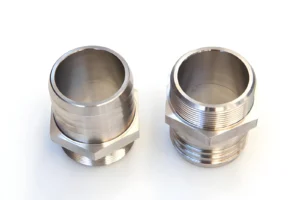
304 stainless steel has a lower thermal conductivity than carbon steel and aluminum, so more heat remains in the cutting zone during machining. It also has high ductility, which makes chips more difficult to break, and it readily work-hardens if the cutting edge does not remove material effectively. These characteristics increase cutting forces, accelerate tool wear, and require machining parameters that differ from those used for free-machining materials.
Proper tool selection, rigid setups, and controlled cutting parameters are essential for reliable stainless steel CNC machining, especially when producing parts with tight tolerances.
What Causes Work Hardening?
Work-hardening is a result of the change in the material’s structure under the influence of plastic deformation at the cutting edge. The layer immediately below the tool that is machined becomes harder than the base material. If this hardened layer is removed in subsequent passes, the cutter will have increased cutting resistance compared to that of the first pass.
Light cuts and worn tools can increase the likelihood of work hardening because they work the surface without removing enough material, and rubbing at the cutting edge can also cause work hardening.
How Work Hardening Affects Cutting
In work hardening, the cutting conditions vary during the cutting process. A hardened surface results in higher cutting forces and cutting temperature, thus reducing tool life. As the cutting edge wears, the chip formation and surface finish could also change. They are more pronounced with prolonged machining operations and repeated finishing operations.
Common 304 Stainless Steel Machining Challenges
304 stainless steel presents several machining characteristics that influence process planning.
- Due to the high ductility of the material, long continuous chips were created.
- Improved cutting temperatures due to heat being kept close to the cutting area.
- Favorable condition of built-up edge of cutting tool.
- High cutting speed as compared to many carbon steels.
- The cutting forces increase due to the occurrence of work hardening.
- More focus on chip removal during deep pockets and holes bored.
Selecting Cutting Tools for 304 Stainless Steel Machining
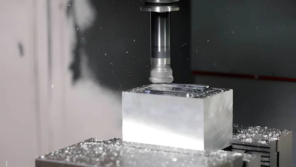
304 stainless steel places continuous load on the cutting edge, so tool selection is based on the machining operation, radial engagement, cutting depth, and chip evacuation. Cutter geometry is often more influential than the cutter diameter because it directly affects cutting pressure and chip formation.
Carbide End Mills
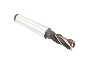
Solid carbide end mills are often used for pocket, side milling, profiling, and finishing. A helix angle of 35-45° is commonly used as it offers a smooth cutting action in stainless steel without compromising the edge strength. Variable helix and variable pitch designs help to minimise vibration during long radial engagement.
4-flute end mills are more effective for roughing applications as they offer more chip space and good removal. In operations that finish the workpiece, they usually use 5-flute or 6-flute end mills to improve the surface quality and increase feed rates. Corner-radius end mills may be more popular than end mills that have sharp corners because they spread the cutting load around the edge of the end mill.
Indexable Milling Cutters
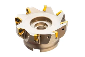
Usually, large facing operations will employ indexable cutters rather than solid carbide tools. 45° lead angle face mills minimize radial cutting forces and distribute cutting forces over a larger edge. When a square shoulder needs to be preserved, shoulder milling cutters with 90° inserts are used.
Therefore, 304 stainless steel is typically better suited to positive-rake inserts, since they have less cutting force and also generate a smoother flow of chips than the negative-rake inserts.
Drills and Reamers
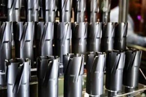
135° split point drills on solid carbide improve centering accuracy, while their reduced thrust force during hole entry helps minimize any damage to the hole walls. Through-coolant drills are often used for holes deeper than 3×D, since the coolant in the holes helps in the removal of chips from the hole.
Reamers are typically used following drilling, when tolerances like H7 or better surface finish are called for. The amount of material removed by the reamer is relatively small, so the hole is drilled with more stock for the finishing operation.
Coatings Used for Stainless Steel Machining
It is not only the material that determines the coating, but also the cutting temperature and cutting conditions.
The coating is selected according to cutting temperature and machining conditions rather than the material alone.
- AlTiN is suitable for higher-speed machining for increased heat resistance.
- In some applications, TiCN is chosen for lower-speed operations where good abrasion resistance is required.
- In production machining, coated carbide tools are more frequently used for finishing operations, but uncoated carbide tools are sometimes used for finishing operations where there is an abundance of coolant.
Cutting Parameters for 304 Stainless Steel
The cutting tool, machining operation, and workpiece geometry all influence the cutting parameters. Cutting speed, feed rate, depth of cut, and coolant should be selected together because changing one value often changes the cutting conditions.
Cutting Speed
The effect of cutting speed is primarily on the cutting edge temperature. The faster the cutting speed, the more heat is created, and the lower the cutting speed, the more likely there will be built-up edge.
Feed Rate
The feed controls the amount of material that each cutting edge removes. Consistent chips will be produced during the operation with a steady feed. The feed should be the same as the cutter diameter, number of flutes, and operation of the machine.
Depth of Cut
The amount of material removed is a function of the depth of cut. Generally speaking, the roughing operation will remove more material than the finishing operation will remove since the depth of cut will be larger.
Coolant Application
Typical applications of coolants include heat control and chip removal from the cutting area. Flood coolant is often employed with milling operations and through-tool coolant is often employed with drilling operations. The coolant should be compatible with the cutting tool and machining process.
Cutting Parameter Summary
| Parameter | General Practice | Machining Consideration |
| Cutting Speed | Follow the cutting tool recommendation. | Controls cutting temperature and tool wear. |
| Feed Rate | Match the cutter and machining operation. | Influences chip formation and cutting load. |
| Depth of Cut | Select according to roughing or finishing. | Changes the amount of material removed per pass. |
| Coolant | Choose the method that suits the operation. | Controls heat and supports chip removal. |
CNC Milling vs CNC Turning for 304 Stainless Steel
304 stainless steel is machined on both CNC mills and CNC lathes during production. The choice depends on the shape of the part and the features shown on the drawing. Many components begin on one machine and move to another before machining is complete.
Milling Operations
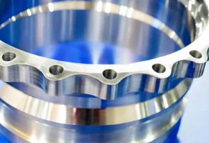
Milling is selected after reviewing the features that cannot be produced by rotating the workpiece. Pockets, keyways, mounting faces, slots, bolt patterns, cross holes, and machined contours are typical examples. During milling, chip evacuation becomes more important in deep pockets because long stainless-steel chips can remain inside the cutting area if they are not removed.
Turning Operations
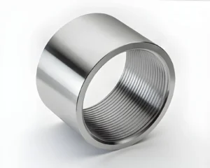
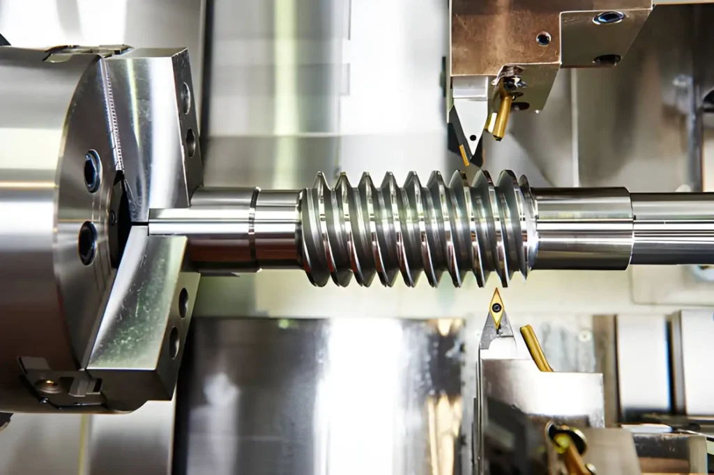
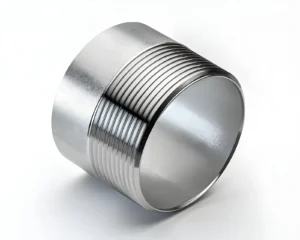
Turning is generally the first operation for parts produced from round bar stock. Outside diameters, shoulders, grooves, internal bores, and external threads are completed before the part moves to any secondary operation. Stable workholding and continuous chip control are commonly reviewed throughout long turning cycles.
Parts That Combine Both Processes
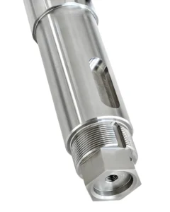
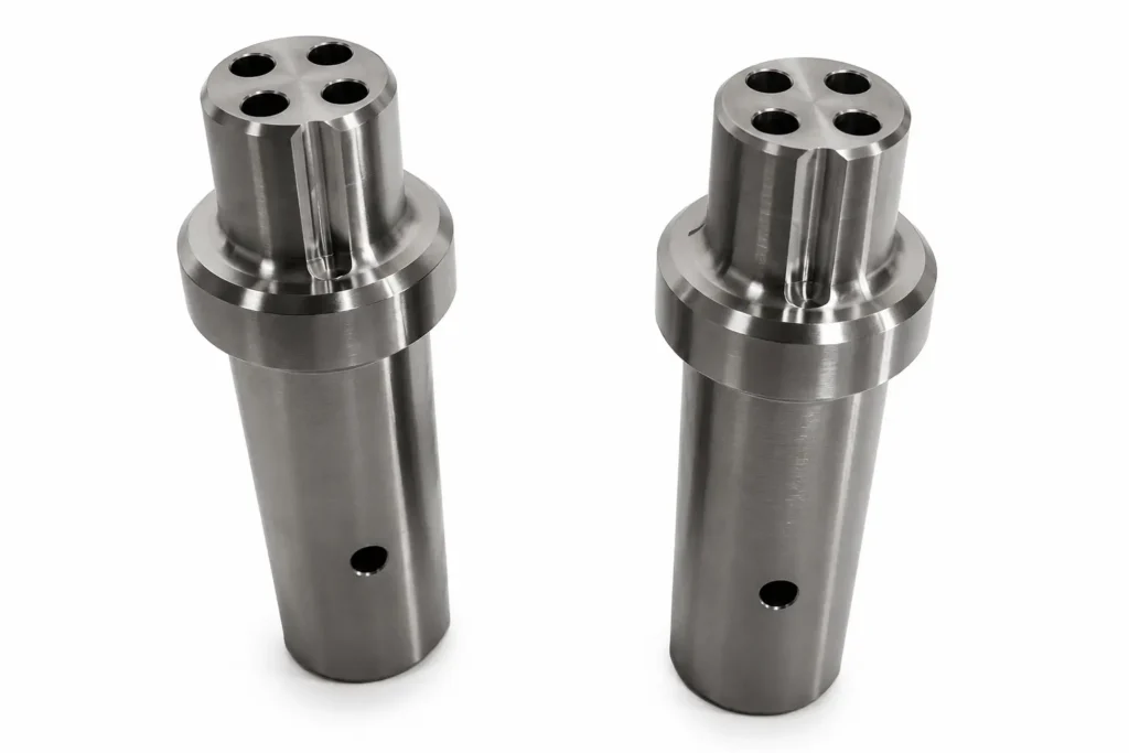
Many 304 stainless steel parts are not finished on a single machine. A valve stem may be turned to size before milling wrench flats. A hydraulic fitting may require turning for the threaded section and milling for cross holes. Sensor housings, couplings, medical fittings, and pump components also combine both machining processes because each operation produces different features more directly.
Comparison Table
| Part Feature | Typical Process |
| Outside diameter | CNC Turning |
| Internal bore | CNC Turning |
| External thread | CNC Turning |
| Wrench flats | CNC Milling |
| Slots and keyways | CNC Milling |
| Cross holes | CNC Milling |
| Bolt hole patterns | CNC Milling |
| Combination parts | CNC Turning + CNC Milling |
Common Problems During 304 Stainless Steel Machining
304 stainless steel usually machines consistently when the cutting process remains stable. Most production issues are related to the cutting tool, chip removal, and heat generated during machining. These conditions are checked regularly during production because they directly affect the finished part.
Excessive Tool Wear
In particular, 304 stainless steel imposes a continuous loading on the cutting edge, particularly in a roughing and long cutting process. The cutting forces will rise as the tool wears, and the material will not be cut as cleanly. Rather than altering the machining program, shops typically check the cutting edge to ensure that the tool has served out its intended service life.
Built-Up Edge
In the cutting process, a small piece of stainless steel may attach to the cutting edge. This alters the shape of the cutting edge and impacts the following cut. The first sign, usually observed on the part, is the presence of burrs at holes, a roughened surface, or slight dimensional changes.
Poor Chip Control
The 304 stainless steel produces long chips that do not break easily. Chips can scratch the surface to be machined, get in the way, or stick in the pocket or near a turning tool. Usually, a first production run is done to test the chip shape before a continuous machining run begins.
Surface Finish Problems
Surface finish should remain similar from the first part to the last. When a finish starts to change, typical first checks are: Cutting tool, spindle runout, work holding, and vibration. These parameters are normally inspected before changing the cutting parameters.
Common Checks During Production
| Issue | First Check |
| Tool wears sooner than expected | Inspect the cutting edge |
| Burrs begin to appear | Check for built-up edge |
| Chips collect around the tool | Review chip evacuation |
| Surface finish changes | Inspect the tool and workholding |
Design Tips for Machining 304 Stainless Steel
The machining process is largely determined by the part drawing. Feature dimensions, cutter access, and tolerance requirements influence tool selection, machining sequence, and the number of setups. Reviewing these points before production usually avoids unnecessary machining operations and secondary work.
Avoid Deep Narrow Slots
Deep slots restrict the range of cutting tools that can be used because the cutting tool must be inserted to the full depth at the blade and not have too much overhang. The wider the slot, the bigger end mill can be used, which will make the tool more rigid and fewer cutting passes will be needed. When the slot size is determined by the design, the slot is usually created in a series of gradually increasing cuts.
Use Practical Internal Radii
Round cutting tools are used for the internal corners. If the rest of the pocket can be cut with a larger end mill, then a very small radius will necessitate the need for a smaller end mill. If the internal radius is the same as the standard cutter size, then the tool selection and change process becomes easier, avoiding the need for an extra tool change.
Allow Enough Tool Access
The movement of cutters is limited in narrow openings, enclosed pockets, and walls that are close together, necessitating the use of smaller tools. There is a clearance between the cutter and tool holder which provides the programmer with more space to machine and will minimize long overhang.
Apply Functional Tolerances
Review each tolerance against the feature’s purpose. Dimensions used for locating, fitting, or sealing usually require closer control.
General outside dimensions and clearance features are often specified with standard machining tolerances.
304 vs 303 vs 316 Stainless Steel
Although 303, 304, and 316 belong to the same stainless steel family, they are selected for different production requirements. The comparison usually starts with the service environment, followed by corrosion resistance, machinability, and fabrication requirements.
303 Stainless Steel
303 is developed to improve machinability. The sulfur added to the material promotes chip breaking and lowers cutting resistance compared with 304. It is commonly selected for shafts, threaded parts, bushings, fittings, and other components produced in larger production volumes.
304 Stainless Steel
304 is recommended for parts that need to have good corrosion resistance in addition to good brazing and welding qualities. It creates longer chips in the machining process and requires more precision in the cutting conditions to obtain constant tool life and surface finish.
316 Stainless Steel
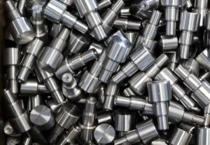
316 is also molybdenum-alloyed, for resistance to chlorides and various chemical environments. It is commonly used in the production of marine equipment, pharmaceutical parts, medical devices, and chemical processing equipment. Machining normally needs lower cutting parameters than 304 due to its higher cutting resistance.
Material Comparison
| Property | 303 | 304 | 316 |
| Main difference | Sulfur added for improved machinability | General-purpose austenitic stainless steel | Molybdenum added for higher corrosion resistance |
| Chip formation | Shorter chips | Longer continuous chips | Longer continuous chips |
| Machinability | Highest | Moderate | Lower than 304 |
| Corrosion resistance | Good | Very good | Excellent |
| Typical components | Shafts, fittings, threaded parts | Housings, brackets, valves, food equipment | Marine, medical, chemical equipment |
Choosing a CNC Machining Supplier for 304 Stainless Steel
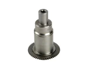
The supplier should be able to machine the part shown on the drawing, inspect the required dimensions, and support the planned production quantity. These points are usually reviewed before requesting a quotation.
Material Experience
Inquire if there are similar 304 stainless steel parts that have been manufactured previously. Experience with the same kind of component is more beneficial than experience with stainless steel.
Tooling Capability
Look over the machining process in conjunction with the supplier. Certain cutting tools and/or machining operations may be needed for deep pockets, thin walls, small internal radii, and long holes.
Inspection Methods
Drawings should be followed by inspection. Some critical bores and threads, some locating faces and geometric tolerances may need to be measured in a different way, and it’s a good idea to verify how each feature will be measured.
Prototype Through Production
If the project goes into production, the same supplier should be able to produce without modifying the machining process or inspection method.
| Review Item | ✓ |
| Similar 304 stainless steel parts | ✓ |
| CNC milling | ✓ |
| CNC turning | ✓ |
| Inspection plan | ✓ |
| Material certificate | ✓ |
| Prototype machining | ✓ |
| Production capacity | ✓ |
Need CNC Machining for 304 Stainless Steel?
At YD Rapid, we manufacture 304 stainless steel components for prototype and production projects using CNC milling and CNC turning. Before machining begins, our engineering team reviews the part drawing to identify machining concerns, recommend practical improvements, and provide free DFM feedback.

As an ISO-certified manufacturer, we support projects from a single prototype to full production and provide a fast quotation based on your drawing and technical requirements.
FAQs
Can 304 stainless steel be machined without coolant?
Some milling operations can be performed without coolant using suitable carbide tooling and cutting conditions. Drilling, tapping, and deeper machining operations commonly use coolant to control cutting temperature and improve chip evacuation.
Why does 304 stainless steel produce long stringy chips?
304 stainless steel has high ductility, so the material tends to form continuous chips instead of breaking into short segments. Chip shape is influenced by tool geometry, feed rate, and chip breaker design.
Which end mill coating is commonly selected for 304 stainless steel?
TiAlN and AlTiN coatings are commonly used for carbide end mills machining 304 stainless steel because they withstand higher cutting temperatures. The final coating selection depends on the machining operation and cutting conditions.
Does cold-worked 304 machine differently from annealed 304?
Yes, cold-worked 304 has higher hardness and strength than the annealed condition. Cutting forces are generally higher, and tool wear may increase during machining.
Can 304 stainless steel be machined after welding?
Yes, welded components are frequently machined after fabrication to finish holes, mounting faces, sealing surfaces, and other critical features. Weld quality and distortion are usually checked before machining begins.
Why is chip evacuation important during deep pocket machining?
Chips that remain inside a deep pocket can be recut by the cutter, affecting surface finish and increasing tool wear. Effective chip evacuation keeps the cutting area clear throughout the machining operation.
Does surface finish change as the cutting tool wears?
Yes, as the cutting edge wears, the tool removes material less consistently. Surface finish, burr formation, and dimensional accuracy may gradually change during production.
Which machining operations are usually completed first on 304 stainless steel parts?
The machining sequence depends on the part geometry. Rough machining is generally completed before finishing operations so that the final dimensions and surface finish are produced after most of the material has been removed.