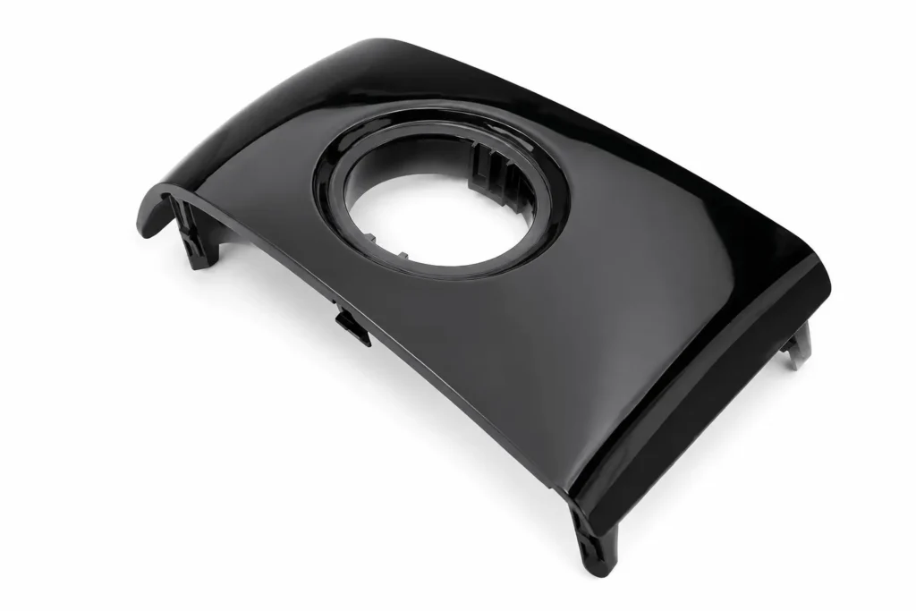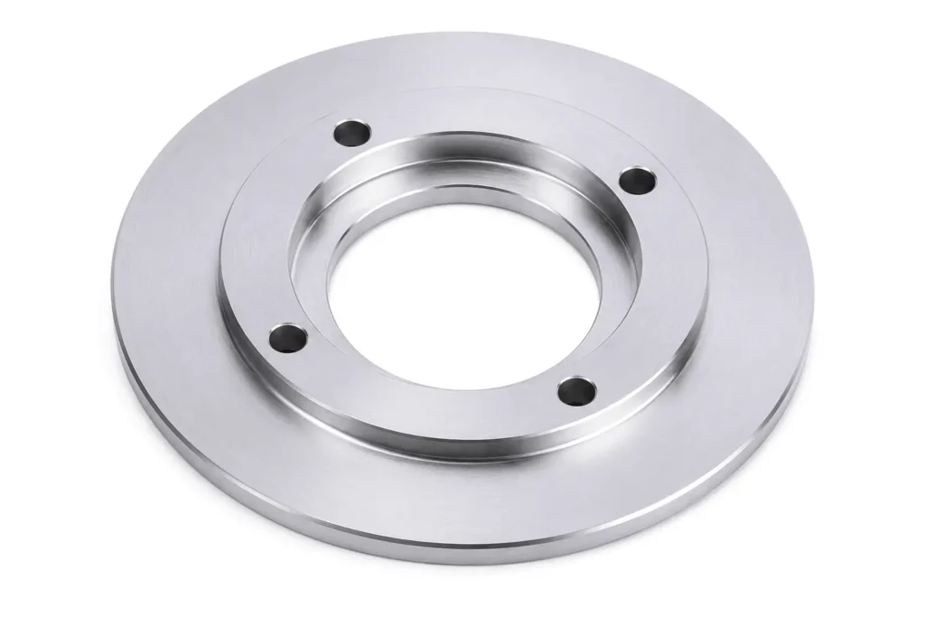
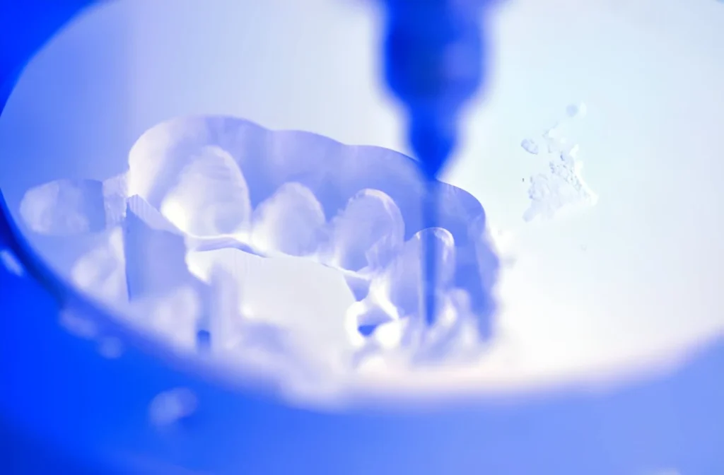
Medical CNC machining is often used for parts that cannot simply be made to a nominal size and sent to assembly. Small features, mating surfaces, holes, threads, and edges may all have specific requirements on the drawing. The material also affects the machining approach, since 316L stainless steel, titanium, and PEEK behave differently during cutting.
A good process starts with the part drawing and its intended function. Material certification, machining strategy, surface finish, inspection, and documentation should be considered before production starts.
This article looks at these practical factors and explains what to check when producing CNC-machined medical parts.
What Is Medical CNC Machining?
Medical CNC machining is the manufacture of medical components using computer-controlled cutting machines. It is used for surgical instruments, orthopedic components, dental parts, diagnostic equipment components, and medical device hardware.
The machining requirements are determined by the part function, material, geometry, and production documentation. The part function determines which features need to be controlled.
Material affects cutting tools, speeds, feeds, and machining conditions. Geometry determines the machine configuration, tool access, workholding, and number of setups. The drawing and CAD model define dimensions, tolerances, surface finish, threads, and other required features.
For production, the manufacturer works from the specified part requirements rather than treating all medical components the same. A small turned component, a machined surgical instrument, and a complex orthopedic part can require different machines, tooling, and inspection methods.
Medical Parts Commonly Made With CNC Machining
Below are the typical medical parts commonly made with CNC machining.
Surgical Instruments
Machined parts include instrument handles, clamps, forceps, scissors, holes, slots, mating surfaces, and contoured features. The actual machining must ensure that the specified dimensions and surface requirements on the drawing are met.
Orthopedic Components
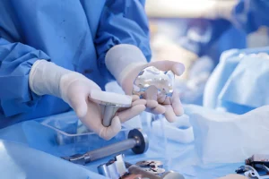
The orthopedic parts are bone plates, screws, fixation components, and other precision parts. These components may feature curves, holes, threads, and intricate geometries.
Dental Parts
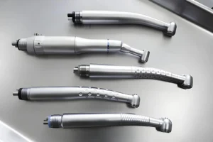
Dental CNC parts include implant frameworks, abutments, surgical guides, and other small precision components. These components frequently entail fine features that require close tolerances.
Parts commonly include fine features and close tolerances.
Diagnostic Equipment Components

The diagnostic equipment that needs machined components ranges from housings to brackets, mounts, shafts, fixtures, and positioning elements.
CNC machining is used for these components when controlled dimensions and accurately located features are required for proper assembly and fit.
Medical Device Hardware
Medical device hardware consists of adapters, connectors, brackets, housings, shafts, and mounting parts. The geometry, material, tolerances, and production quantity determine the required machining method.
CNC Processes Used for Medical Parts
The CNC process selection is based on the part geometry, part specifications, tolerances, and production requirements.
CNC Milling
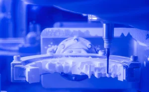
CNC milling is utilized for parts containing pockets, slots, holes, flat surfaces, and contoured surfaces. The workpiece is supported during rotation to remove material with cutting tools. Many parts for surgical instruments, orthopedic and dental parts, and medical device hardware are suitable for milling.
CNC Turning
CNC turning is primarily used for cylindrical parts. The rotating workpiece is cut to produce outside diameters, bores, grooves, threads, etc., that are rotated. Shafts, pins, sleeves, screws, and other similar parts are common uses.
5-Axis Machining
5-axis machining is employed for parts requiring complex surfaces, angled features, or parts that are hard to access with 3-axis machining. The extra rotary axis gives the tool greater access to the workpiece from various directions and can help minimize setups and access to complex features.
Swiss Machining
Small-diameter and fine-length parts are suitable for Swiss machining. The material is supported near the cut area, which helps control deflection during cutting. It is frequently employed in the manufacture of small pins, screws, shafts, connectors, and other miniature parts, especially when producing large quantities.
Materials Used for Medical CNC Machining
The material to be used is determined by the part function and how it is to be machined. Stainless steel, titanium, and engineering plastics are common materials used for making medical CNC parts.
Typically, engineers consider strength, corrosion resistance, weight, wear, temperature, and dimensional considerations when choosing the material. The material also influences cutting tool, feed, speed, and coolant parameters.
Stainless Steel
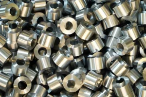
Typically, 316L and 17-4 PH stainless steel are used on medical parts that are machined. 316L has good corrosion resistance, and it is used in components of surgical equipment, fittings, housings, and medical hardware. It is relatively easy to machine, but it can work-harden.
17-4 PH has higher strength than 316L and can be heat-treated to increase its hardness and strength. It is used to build up higher mechanical strength for parts. The heat-treatment condition will influence the material’s machinability; therefore, this is important to know before manufacturing.
Titanium
Ti-6Al-4V is employed in parts that require high strength with low weight addition. It also possesses good corrosion resistance properties and is usually utilized for orthopedic parts and other parts in the medical field.
Titanium has a higher difficulty level to machine than several steels. Not a good heat conductor from the cutting area to the tool, heat may accumulate at the tool. Optimum speed, feed, tooling, and coolant must be chosen carefully to ensure heat and control tool wear.
Medical-Grade Plastics
Engineering plastics like PEEK, PEI, and PTFE are used for many medical components. PEEK is strong, chemical-resistant, and temperature-resistant. PEI has good dimensional stability and temperature performance.
PTFE has extremely low friction and excellent chemical resistance, but is softer and may be easily deformed when it is being machined.
Plastic parts also have different properties than metal when machine-shaped. The final dimensions may be influenced by heat and/or thermal expansion, particularly for thin or small parts.
Material Certification and Traceability
Materials used for a medical part should be traceable to the original material documentation. The typical material certificate will specify the grade of material and include necessary chemical and mechanical test results.
The heat number or lot number is used to link the material to its certificate. When the material is cut up into smaller pieces, this identification should be transferred or recorded so that it can still be identified during the production process.
The drawing, purchase order, or the quality should specify the requirement for material certification and traceability. These records should be kept from the receipt of the material to the time it is machined and inspected.
Tolerances and Surface Finish for Medical Parts
The drawing defines the dimensions and surface requirements that the manufacturer needs to produce and inspect. For medical CNC parts, these requirements should be tied to the way the component fits, moves, seals, or locates in the assembly.
A tight tolerance should be used where the function requires it. Applying tight tolerances to every dimension can increase machining and inspection requirements without improving the part.
Dimensional Tolerances
The tolerance should be the same as the fit required between mating parts. For instance, if a shaft is inserted into a bore, the diameters of both the shaft and the bore must be controlled.
A mounting hole might require a controlled location, but it doesn’t have to be a tight hole diameter. If an outside dimension is not functional, it can often have a larger tolerance.
Therefore, the drawing should include the dimensions that affect the fit or function of the part. The manufacturer can then choose the types of machining processes and checks required to meet those limits.
GD&T Requirements
GD&T can be useful when the relationship of the features includes not only their size but also their relationship. Position is generally used to specify the location of holes in relation to datums. Flatness refers to the shape of a surface without using another feature.
Perpendicularity affects the direction of a surface or feature with respect to a datum. When the design calls for a relationship between specified centres or axes, the concentricity control will be used to regulate that relationship.
It matters that the structure of the datum is. When designing a tolerance like hole position, the position of the hole must be related to the specified datum references, and the drawing must clearly define the datums and the geometric controls.
Surface Roughness
Surface finish should be specified based on the use of the surface. It may be necessary to control the finish on a mating surface so that the parts fit together accurately. For the intended movement and wear, a suitable finishing may be necessary for a sliding surface. A sealing surface must have a certain Ra to ensure a certain contact with the mating seal or surface.
Ra is commonly used to specify surface roughness. The value required should be specified on the drawing and not assumed as a standard CNC finish for a surface.
Burr and Edge Control
Frequently, burrs are found on drilled holes, slots, pockets, and cross-cutting features. Should they not be removed, they may be a hindrance to assembly or stay on the surface where they are not wanted.
Edge condition is also relevant when handling, assembling, cleaning, or fitting the part with another part. A chamfered or rounded edge may be necessary for a sharp edge, and deburring may be needed for a hole after it has been cut.
The drawing should show what the edge condition is where it is important. A callout like 0.2 mm max edge break, 0.5 × 45° chamfer, or a specific edge radius provides a measurable requirement rather than one that leaves the edge condition open to interpretation.
CNC Machining Considerations for Medical Parts
Some medical parts are difficult to machine because they have small features, thin walls, deep holes, or complex shapes. These features need to be considered before machining because they can affect part accuracy and the final surface.
Tool Selection and Cutting Conditions
The cutting tool and the machining conditions should be appropriate to the material being cut. There are different tools and cutting criteria for different materials, such as stainless steel, titanium, and plastics.
Titanium requires special heat control since it has poor heat dissipation properties. If the tool rubs against the material, it can harden stainless steel. The cutting conditions have to be carefully controlled for plastics, as excessive heat can alter their dimensions.
The size of the tool is also a function of the feature. For narrow slots and small holes, small tools will be needed, and for deep features, longer tools will be needed.
Workholding
The part should be fixed firmly and without altering its form. This is particularly true for thin walls and small parts.
Excessive clamping pressure may cause the deformation of a thin section. Once the part is removed from the fixture, it could regain its original shape and no longer be within the specified dimensions.
The fixture should hold the part in such a way that it is held securely and allows for easy access to the features to be machined on the part.
Small Holes and Deep Features
Small and shallow holes demand special drilling techniques and chip extraction. If it is difficult to remove the chips from the hole, it may cause damage to the drill and the surface of the hole.
The drawing should include hole dimensions such as hole diameter, depth, location, and tolerance. The drilling and inspection method is determined by these requirements.
Thin Walls and Complex Geometry
Thin walls will move with material removal. You can help minimize movement by leaving behind some material to support and then machining the thin part later.
More tool access is also required for complex shapes. Smaller cutters and/or another setup, or a 5-axis, may be necessary for deep pockets, narrow areas, and angled surfaces.
The machining sequence should be designed to ensure that the part is stable through important features.
Inspection and Quality Control
The engineering drawing is the first project to be inspected. At the end of the process, the manufacturer verifies dimensions, tolerances, GD&T, surface finish, material grade, and other requirements against the specified values.
Each feature will use a different inspection method. The diameter of a shaft can be measured using a micrometer, and some holes may need a CMM. What’s crucial is that the measurement procedure should be appropriate for the tolerance being measured.
First Article Inspection
First Article Inspection (FAI) is a method of examining the first production part against the entire drawing before acceptance of the production process for the remaining parts.
The required drawing characteristics and the measured results are outlined in the inspection report. These may range from dimensions, hole location, GD&T, surface finish, threads, and material specification.
FAI is particularly significant if the part is new or if a change in the drawing, material, process, or manufacturing location could impact the finished part.
CMM Inspection
A CMM is normally used for features where accurate location or geometric relationships are important.
For instance, a CMM may measure hole patterns from the drawing datums, the profile of a machined surface, or the position and orientation of features specified by GD&T.
The datum structure and GD&T identified on the drawing should be followed when using the CMM inspection for these measurements. Checking the proper size is not a sufficient indicator of feature location.
Dimensional Inspection
Different features require different measuring equipment.
- Micrometers: Outside diameters, thicknesses, and other close-tolerance dimensions.
- Calipers: General dimensions where the tolerance permits their use.
- Bore gauges: Controlled internal diameters.
- Pin or plug gauges: Hole sizes and production checks.
- Thread gauges: Internal and external threads.
- Optical systems: Small features, profiles, and dimensions that are difficult to measure with contact tools.
- Surface roughness testers: Ra requirements on specified surfaces.
For a critical dimension, the measuring equipment should have sufficient accuracy to determine whether the part is actually within the drawing tolerance.
Inspection Documentation
The inspection records should identify what was measured, which drawing revision was used, and what material was used.
Depending on the order requirements, the quality package may include:
- First Article Inspection Report
- Dimensional inspection report
- CMM report
- Material certificate
- Certificate of Conformity
- Surface roughness report
- Calibration records
- Required test or process certificates
The material certificate should correspond to the material supplied for the job. It normally identifies the material grade and heat number or lot number, along with the chemical and mechanical results required by the material specification.
Surface Finishing for CNC Machined Medical Parts
The finish should match the material and the job of the surface. Stainless steel parts may need passivation, aluminum equipment parts may be anodized, and selected surfaces may need polishing or electropolishing. The drawing should state the required finish and identify any surfaces that need special treatment.
Passivation
Passivation is used mainly on stainless steel after machining. It removes free iron and other contaminants left on the surface during machining and helps maintain the corrosion resistance of the stainless steel.
316L stainless steel parts are commonly passivated when corrosion resistance and surface cleanliness are required. The part should be cleaned before passivation to remove machining oil, chips, and other contamination.
Electropolishing
Electropolishing is the process of removing a small amount of metal from the surface, resulting in a surface that is smoother than the surface created by normal machining.
It is applied to specific parts made from stainless steel where a smoother surface and cleaner metal surface is desired. Small features and dimensions may be affected by the process, and critical tolerances should be checked when electropolishing is used.
Anodizing
Anodizing is used mainly for aluminum components. It can create a protective oxide film on the surface and enhance corrosion and wear resistance.
It can be applied to non-implant parts like aluminum housings, brackets, handles, and more for medical equipment. If they impact the part or its fit, the anodizing type and thickness should be indicated.
Polishing
Polishing is applied to create a smoother surface than that provided by a standard CNC machine. It may be included for instrument surfaces, mating surfaces, or other parts of the instrument requiring it.
Polishing is recommended only on the necessary surfaces. These areas should be identified in the drawing, and the finish indicated so that the polishing does not affect edges and dimensions that are important to the part.
Design Considerations for CNC Medical Parts
Medical parts should be designed with the machining process in mind. Hole depth, wall thickness, internal radii, and tolerances can all affect the tools required, number of operations, inspection time, and overall machining cost.
Holes, Threads, and Internal Features
Hole diameters and depths should be feasible with the equipment at hand. As a general rule, a hole shall be considered as being easy to machine if the depth of the hole is 4 times or less than the width of the hole. For instance, a hole of Ø5 mm at 20 mm depth is easier to work with than a hole of Ø5 mm at 50 mm depth.
The longer the hole is to be drilled, the more important it is to use longer drills, provide proper chip removal, and maintain optimum drilling conditions in deep holes. If a hole or thread is needed in a blind hole, leave extra depth below the hole or thread for the drill point.
For internal threads, use size, pitch, and depth. If, for instance, the manufacturer is to be expected to make a requirement of M6 × 1.0, 10 mm deep, then he will know what he is looking for. Don’t use a thread that is too deep, as it increases the machining time and has no advantage in the assembly.
Space should also be allowed around holes and internal features for the cutting tool to enter and for chip clearance. If a hole is positioned near a wall, pocket, or other feature, the size of the hole may need to be reduced, or the type of machine setup may need to be altered.
Wall Thickness
The very thin walls can move during cutting operations and can even change dimensions when the part is removed from the fixture.
A thickness of approximately 1.5 mm or more is easier to machine for general CNC machining than a very thin section. Walls that are less than 1 mm require special attention and may have to be cut lighter, with extra support added or a different machining sequence used.
Actual minimum thickness will vary based on material, wall height, part size, and tolerance. A tall 1.5 mm wall is less rigid and more difficult to hold compared to a short 1.5 mm wall.
If possible, leave thicker supporting material when the initial rough cuts are being made, and finish the thin wall afterwards. This helps to minimize movement during material removal.
Internal Corners and Radii
A standard end mill is rounded and will not give a perfectly sharp internal corner. Therefore, the internal radius should be related to the cutter used.
Try, for instance, an R2 mm internal corner, which can generally be achieved with a Ø4 mm cutter. A reduced radius can lead to a smaller cutter and longer machining time, and affect the rigidity of the cutter.
If possible, use a functional internal radius instead of a 90° corner. A radius of R1 mm, R2 mm, or larger is more readily produced than a very small radius.
Other factors that can restrict tool access include deep pockets with small internal radii. It is important to consider the radius, pocket depth, and cutter diameter in conjunction.
Tolerance Selection
Tolerances should be based on the part function. Avoid setting strict tolerances on all dimensions. Example: If the dimension is a general non-functional dimension, then ±0.10mm may be acceptable, whereas a mating diameter may need to be tighter, such as ±0.02mm, depending on the required fit and machining process.
A tolerance of ±0.01 mm should only be specified when the function requires it. Maintaining this tolerance may involve using more sophisticated machines, careful machining processes, extra finishing processes, and more thorough inspection.
The drawing should describe the dimensions that control fit, location, movement, or function. Other dimensions can be given a reasonable tolerance, and the cost of machining and inspection can be lowered without affecting the performance of the part.
How to Choose a Medical CNC Machining Supplier
The supplier should be able to show that its machining, inspection, material control, and documentation processes match the requirements of the part.
Before production, engineers and purchasing teams should confirm what the supplier can do in-house and what is handled by outside processors.
CNC Equipment and Machining Capabilities
Don’t assume that the supplier has the machines you need for the part; look at a list of their CNC capabilities instead.
Perhaps a complex 3D surface part would be better made using 5-axis machining, or maybe a small turned part would be more suitably produced using Swiss machining. Inquire about the machine’s dimensions, axis capabilities, tolerances, and the materials that it is commonly used to machine.
The supplier should also be able to describe how the part will be manufactured, the primary manufacturing operations, workholding, secondary operations, etc.
Material Sourcing and Traceability
Ensure that the material is obtained from and kept as identified through the manufacturing process.
If the material is a controlled material like 316L, 17-4 PH, or Ti-6Al-4V (titanium), request the relevant material certificate and verify that the material grade is the same as per the drawing or purchase specification.
Heat or lot number should be permanently recorded on the material certificate following the separation of stock into individual blanks. This gives good documentation of what material was used to make the finished parts.
Inspection Equipment
The supplier should be equipped to inspect for the tolerances and features drawn. Ask if they have any CMMs, micrometers, bore gauges, optical inspection equipment, surface roughness testers, or thread gauges as needed on the part.
If GD&T is controlled, ensure that the supplier is capable of measuring the necessary datum relationships and can provide the results of the measurements. A supplier should not use calipers for a feature for which a more precise measurement technique is available.
Surface Finishing
Ensure that required finishing processes are carried out in-house or by a qualified outside supplier. If you are faced with passivation, electropolishing, anodizing, or polishing, inquire about how the process is defined, monitored, and documented. The supplier is also responsible for taking into consideration the impact of finishing on critical dimensions and surfaces.
In cases where a part is subcontracted for finishing, the finished part must be traceable to the appropriate processing record or certificate.
Documentation and Quality Records
Before production, agree on the quality documents that will be supplied with the parts. Depending on the order, these may include:
- Material certificates
- First Article Inspection (FAI) report
- Dimensional inspection report
- CMM report
- Surface roughness report
- Certificate of Conformity (CoC)
- Finishing certificates
- Calibration records
- Heat or lot traceability records
The supplier should also control drawing revisions so that machining and inspection are performed against the correct revision.
Prototype and Production Capacity
A supplier should be able to support the required production stage, from prototype quantities through repeat production.
For prototypes, check whether the supplier can review the CAD model and drawing, identify machining problems, and produce the required features without unnecessary tooling or process changes.
For production, confirm available machine capacity, inspection capacity, typical lead times, and how repeat orders are controlled. The supplier should be able to reproduce the approved part consistently rather than treating every order as a new job.
Medical CNC Machining Services
YD Rapid provides CNC machining for medical components from prototypes to production parts. We work from customer drawings and 3D CAD files and review the part requirements before machining.
Our services include material sourcing, CNC milling, CNC turning, 5-axis machining, dimensional inspection, and surface finishing. Material requirements such as grade, heat number, and certification can be maintained when specified by the customer.
Inspection is based on the drawing requirements. Depending on the part, this can include dimensional inspection, CMM measurement, GD&T inspection, thread inspection, and surface roughness checks.
YD Rapid can also arrange required finishing processes such as passivation, electropolishing, anodizing, and polishing. Inspection reports, material certificates, finishing records, and other quality documents can be supplied according to the project requirements.
The same machining process can support prototype parts, first articles, and production quantities, with the process and inspection plan adjusted to the part and order volume.

FAQs
What materials are commonly used for medical CNC machining?
Common materials include 316L and 17-4 PH stainless steel, Ti-6Al-4V titanium, PEEK, PEI, and PTFE. Selection depends on the required strength, corrosion resistance, temperature resistance, and application.
What CNC processes are used for medical components?
CNC milling and turning are used for most medical components. 5-axis machining suits complex shapes, while Swiss machining is useful for small and slender parts.
How are CNC-machined medical parts inspected?
The inspection method depends on the feature and tolerance. Micrometers, gauges, optical systems, and CMMs can be used for dimensions, hole locations, profiles, and GD&T requirements.
What surface finishes are used for medical components?
Common finishes include passivation, electropolishing, anodizing, and polishing. The choice depends on the material and the required surface condition.
Is titanium difficult to CNC machine?
Ti-6Al-4V requires more control during machining than many steels. It retains heat around the cutting area, which can increase tool wear and requires suitable tooling and cutting conditions.
Why is material traceability important for medical parts?
Traceability connects the finished part with the material used to produce it. Heat or lot numbers and material certificates provide the record needed to identify the material source.
How should tolerances be specified on medical part drawings?
Tolerances should be based on the function of each feature. Tighter limits are used where they affect fit, location, movement, or sealing, while non-critical dimensions can have wider tolerances.
Can CNC machining be used for medical prototypes?
CNC machining is well suited to medical prototypes because parts can be produced directly from the CAD model and engineering drawing without dedicated production tooling.
What is first article inspection for medical CNC parts?
First Article Inspection checks the first completed part against the approved drawing and production requirements. It verifies the dimensions, tolerances, and other specified features before regular production continues.