CNC milling uses a rotating cutter which remains fixed and the table moves along a set toolpath. Cutting direction depends on the spindle rotation, aligning with the feed motion. This creates two setups: climb milling vs conventional milling.
In climb milling (down milling), the cutter moves in the same direction as the feed. The edge enters the material first and starts cutting immediately. In conventional milling (up milling), the cutter moves against the feed direction. The edge contacts the surface with a light rubbing stage before full chip removal begins. This behaviour appears across 3-axis, 4-axis, and 5-axis machining work. Features like flat surfaces, deep pockets, side walls, and curved surfaces do not react the same way during cutting. Therefore, engineers look at tool movement, machine condition, and part setup before selecting a cutting approach.
This article explains how cutting forces behave in both methods, how tool wear develops during machining, and practical points used to select a suitable approach based on machine condition, material type, and dimensional requirements.
What Is Climb Milling and How Does It Work?
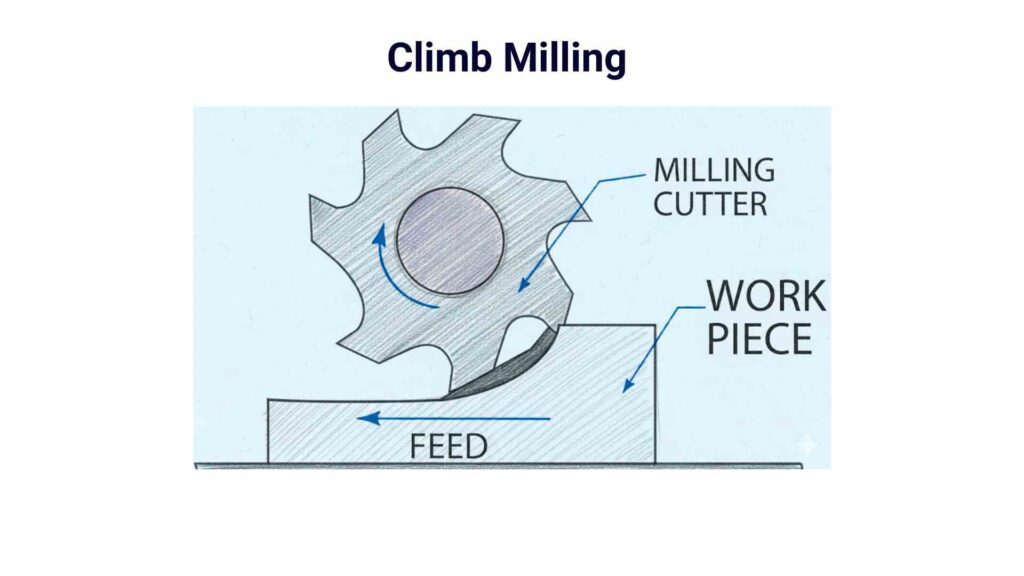
Climb milling is also known as down milling. It involves a cutter that rotates in the same direction as the machine feed movement. The tool and feed travel together. So the cutting edge enters the material at the maximum chip thickness and gradually exits with a smaller chip.
During the cut, the cutter pulls itself into the workpiece instead of pushing against it. This changes how force moves through the tool, spindle, and machine table. Tool contact starts with a heavier engagement and reduces as the cutter leaves the cut.
The process follows a simple movement sequence:
- The cutter rotates in the same direction as the feed travel
- The cutting edge contacts the material immediately
- Material removal starts with a thicker chip section
- Chip thickness reduces as the tool exits the cut
- Cutting force pulls the workpiece toward the cutter path
Tool movement also changes machine behaviour. On modern CNC systems, servo control keeps feed movement stable. However, machine backlash still receives attention. Backlash is the small clearance between moving mechanical parts. If a machine contains excessive backlash, the cutter can suddenly pull into the material and create unstable movement.
What are the Advantages of Climb Milling?
Climb milling is widely used in CNC machining because cutter behaviour changes during material removal. The effect becomes noticeable during profile cuts, finishing work, and repeated machining operations.
Smoother Cutting During Surface Passes
Surface passes often need steady cutter movement. In many machining operations, climb milling helps maintain a smoother cut along walls and external profiles.
Better Chip Removal During Machining
Chip movement affects the cutting area during long tool paths. Cleaner chip flow helps keep the cutting zone from filling with material during machining.
Useful for Finishing Operations
Many shops use climb milling during finishing passes. It is commonly selected for machined walls, profiles, and visible surfaces after rough cutting work.
Supports Complex CNC Tool Paths
Modern parts include curves, pockets, and changing tool directions. Climb milling works well with programmed tool movement across 3-axis, 4-axis, and 5-axis operations.
Helps During Thin Feature Machining
Thin sections and narrow features can react during cutting. Machining teams often use climb milling during lighter passes on these areas.
Common on Modern CNC Machines
Current CNC systems control feed movement accurately. This allows climb milling to run more smoothly compared with older machine setups.
What Is Conventional Milling and How Does It Work?
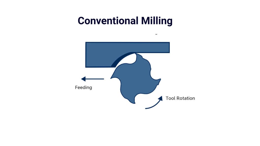
Conventional milling is a cutting method where the cutter rotates against the feed direction. The tool does not enter the material with the full cutting load. Instead, it starts with a light rubbing contact and builds up engagement as the cut continues.
This method follows a clear cutting sequence during machining:
- The cutter touches the surface first with a low chip load
- Material contact increases as the tool moves forward
- Chip thickness grows toward the exit of the cut
- Cutting force builds gradually during engagement
During this process, the tool pushes slightly against the material before full chip removal begins. This creates a different load pattern on the cutting edge compared to other milling directions.
On CNC machines, movement is controlled along X, Y, and Z axes, depending on the toolpath. In 3-axis work, it is often used for straight slotting and rough surface removal. In 4-axis and 5-axis setups, it appears in specific toolpath sections and controlled entry is needed.
Process stages usually follow this pattern:
- The tool approaches the material surface
- Initial contact occurs with light engagement
- Chip thickness increases along the cut path
- Material is removed toward the end of the tool pass
- Cutter exits after the full engagement phase
10 Major Differences Between Climb Milling Vs Conventional Milling
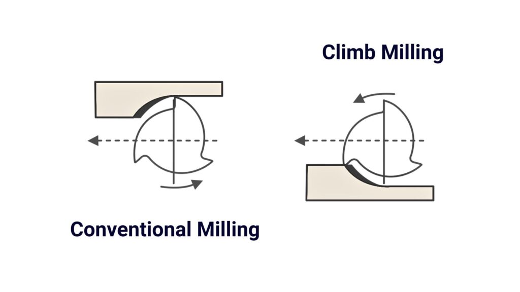
Climb and conventional milling differ in how the cutter interacts with material during feed movement. Although both remove material using a rotating tool, the cutting sequence changes force direction, chip behaviour, and stability during real CNC machining.
1. Feed Direction Relationship
In climb milling, the cutter and feed move in the same direction. As a result, the tool engages the material in a forward pulling motion.
On the other hand, conventional milling moves against the cutter rotation, so the tool presses into the material before cutting fully begins.
2. Cutting Load Development
Climb milling applies full chip load at the start of engagement, then reduces it toward exit. Therefore, cutting stress reduces gradually during tool travel.
In contrast, conventional milling starts with a light load, and then the pressure increases as the cutter moves forward into deeper engagement.
3. Surface Interaction at Entry
During climb milling, the tool edge meets the material directly and starts removing chips instantly. This avoids surface dragging at entry.
Whereas in conventional milling, the cutter slightly rubs before full chip formation begins, which changes surface interaction at the start of the pass.
4. Direction of Cutting Force
Climb milling produces a pulling effect where force tends to draw the tool into the cut. This keeps the load closer to the cutting zone.
However, conventional milling pushes the cutter away from the material, which increases outward pressure during cutting.
5. Behaviour on Thin Structures
In climb milling, the cutting force stays more controlled during finishing passes, so thin walls show less movement in many cases.
Meanwhile, conventional milling can push material away slightly before full cutting develops, especially on light structures.
6. Response to Machine Backlash
Climb milling depends strongly on axis control. Even small mechanical clearance can affect tool motion, especially on older machines.
Conventional milling behaves more forgivingly because the force direction opposes feed motion instead of pulling into it.
7. Chip Flow Pattern
Climb milling directs chips away from the cutting zone more naturally as the tool exits with a lighter load. Conversely, conventional milling can keep chips near the entry area longer before they are fully cleared from the tool path.
8. Tool Engagement Stability
Climb milling maintains more direct engagement once cutting starts, which supports steady finishing passes.
In contrast, conventional milling builds engagement gradually. It remains more stable in rough cutting conditions.
9. Wear Distribution on Tool Edge
In climb milling, tool wear tends to spread across the cutting edge during continuous passes. Whereas in conventional milling, wear is more concentrated near the entry side due to initial rubbing contact.
10. Suitability Across CNC Operations
Climb milling is often selected for finishing and precise contour work in modern CNC setups. Meanwhile, conventional milling is still used in roughing operations and setups where machine rigidity or older systems require controlled engagement.
Summary Table
| Parameter | Climb Milling | Conventional Milling |
| Chip load profile | Max → Min along cut | Min → Max along cut |
| Force vector direction | Into fixture side/pull-in effect | Away from the cut / push-out effect |
| Entry cutting mode | Pure shear initiation | Ploughing + shear transition |
| Spindle load trend | Stabilises after entry | Gradual increase during the cut |
| Deflection tendency | Lower in finishing thin walls | Higher in light structures |
| Backlash sensitivity | High (directional pull-in effect) | Lower (opposing force direction) |
| Chip evacuation path | Rearward discharge flow | Forward + local accumulation risk |
| Wear concentration | Distributed along the cutting edge | Entry-side localized wear |
| Surface generation mode | Direct shear dominant | Mixed plough + shear zone |
| Machine suitability | High rigidity CNC systems | Lower rigidity / roughing setups |
Best Material Applications: Climb vs Conventional Milling Behaviour
In climb milling, chip flow and cutting load stay more controlled in ductile materials, while in conventional milling, harder or uneven materials handle the gradual load build-up more safely during cutting.
Ductile Metals (Aluminum, Stainless Steel, Brass, Soft Alloys)
Examples: Aluminium (Al), Stainless Steel (SS), Brass, copper-based soft alloys
In ductile materials, climb milling generally gives more stable chip formation. The cutting edge engages cleanly, so chip shear dominates over rubbing. This reduces built-up edge in aluminium and brass, especially at higher spindle speeds.
- Aluminium shows smooth chip evacuation, but heat can accumulate at higher feeds.
- Stainless steel reacts with work hardening, so stable engagement reduces surface tearing.
- Brass cuts cleanly, so climb milling improves edge definition in profiling
Conventional milling in ductile materials often increases rubbing at the entry. This can slightly raise the tool load before full chip separation, especially in softer alloys.
Harder Metals, Castings, and Scaled Surfaces
Examples: Hardened steel, cast iron, oxidised or scaled forged surfaces
In harder and non-uniform materials, conventional milling is often used in roughing passes. The gradual chip load increase helps absorb surface interruptions and hard spots during entry.
- Cast iron breaks chips easily, but the surface scale causes intermittent cutting load.
- Hardened zones in steel increase tool stress during sudden engagement
- Scale on forged parts can create impact loading on the cutter edges
Climb milling in these conditions can create sudden load changes if the cutter hits hard surface sections directly. This affects tool stability in interrupted cuts.
Thermal Expansion and Workpiece Stability
Material temperature response also affects milling choice.
- Aluminium expands faster, so stable chip flow in climb milling helps control heat buildup during continuous passes.
- Stainless steel retains heat in the cutting zone, so controlled engagement is important to avoid localised stress.
- Castings may have uneven thermal zones, so conventional milling can reduce sudden engagement shock.
Workpiece stability becomes critical in thin or unsupported sections. Materials that deform under heat or cutting load respond better when force is distributed gradually rather than applied in a single engagement spike.
Climb Milling vs Conventional Milling: When to Use Each
When to use Climb Milling(Down Milling)
- Choose climb milling for finishing passes on rigid CNC setups with stable axis control, because the cutter engages the surface directly without rubbing at entry.
- Employ it for aluminium and brass parts where smooth chip flow is needed, since chips exit cleanly without sticking near the cutting edge.
- It is best for pocket walls and profile finishing if the edge condition must stay clean, because cutting starts immediately at the contact point.
- Use it for thin-wall finishing on stable fixtures, since the cutting force stays directed into the workholding instead of pushing the part outward.
- It is optimal for high-speed contouring and surface finishing toolpaths because the tool load stays more consistent after engagement.
When to use Conventional Milling(Up Milling)
- Use conventional milling for roughing operations with heavy stock removal, because chip load increases gradually and reduces sudden cutting impact.
- Use it on machines with backlash in axis movement, since cutting force works against the feed direction and reduces pull-in risk.
- Use it for cast iron, forged parts, and oxidised surfaces, because gradual engagement handles surface variation more safely.
- Use it for interrupted cuts such as slots and cross features, since the tool meets material in controlled steps instead of full engagement.
- Use it for deep roughing passes, because load builds progressively and keeps tool engagement more stable during entry and exit transitions.
CNC Feed/Speed Reference: Climb vs Conventional Milling
Feed and speed values change based on cutter engagement behaviour. Climb milling allows more stable chip separation in most ductile materials, while conventional milling builds load gradually and needs controlled entry settings. The values below are practical shop-floor ranges used in general CNC production.
CNC Feed & Speed Reference Table
| Material Group | Milling Direction | Spindle Speed (RPM) | Feed per Tooth (mm/tooth) | Depth of Cut (mm) | Cutting Behaviour Note |
| Aluminum alloys | Climb | 9000 – 18000 | 0.06 – 0.22 | 0.5 – 3.0 | Stable chip flow supports higher feed in finishing |
| Aluminum alloys | Conventional | 7000 – 15000 | 0.04 – 0.14 | 0.5 – 2.5 | Entry rubbing limits aggressive feed |
| Stainless steel | Climb | 3000 – 8000 | 0.03 – 0.10 | 0.3 – 2.0 | Heat builds, needs stable engagement |
| Stainless steel | Conventional | 2500 – 7000 | 0.02 – 0.08 | 0.3 – 1.8 | Gradual load rise reduces shock at entry |
| Mild steel | Climb | 5000 – 10000 | 0.05 – 0.16 | 0.5 – 3.5 | Good balance of finish and chip flow |
| Mild steel | Conventional | 4000 – 9000 | 0.04 – 0.12 | 0.5 – 3.0 | More stable during rough passes |
| Cast iron | Climb | 2500 – 6000 | 0.03 – 0.10 | 0.5 – 2.5 | Chips break easily, stable cutting is needed |
| Cast iron | Conventional | 2000 – 5500 | 0.02 – 0.08 | 0.5 – 2.0 | Handles surface scale and interruption better |
| Brass | Climb | 10000 – 20000 | 0.08 – 0.30 | 0.5 – 3.0 | Very smooth cutting, low burr formation |
| Brass | Conventional | 8000 – 18000 | 0.05 – 0.20 | 0.5 – 2.8 | Slight entry friction, but still stable |
Tips for Optimizing Climb and Conventional Milling in CNC Machining
- Use climb milling in finishing cycles when machine rigidity is stable, since chip flow stays consistent and surface marks reduce on profile walls
- Reduce feed per tooth in stainless steel during conventional milling, because chip load increases toward the exit and heat builds quickly
- Increase spindle speed first before increasing feed in aluminium, especially in climb milling, to maintain smooth chip evacuation
- Keep the depth of cut moderate in conventional milling for thin features. Since force builds gradually and can shift a part’s position
- Use climb milling for contour finishing instead of roughing, since it performs better after stable engagement is established
- Avoid aggressive step-over in cast iron during climb milling, since surface hardness variation can change the load suddenly
Get CNC Milling Support from YD Rapid, Backed by Decades of Experience
YD Rapid provides CNC machining support for both climb and conventional milling strategies. We work with aluminium, stainless steel, brass, and engineering-grade alloys using controlled cutting paths based on geometry and material response.
Before production, we review tool engagement, cutting direction, and load distribution. This helps stabilize machining during roughing and finishing stages and reduces cutting variation across batches.
Upload your CAD file and get machining support from our engineering team for CNC milling projects, prototypes, and production parts.

FAQs
Why do CNC programs switch between climb and conventional milling in one part?
Because different features behave differently. Rough pockets may need conventional milling, while outer profiles need climb milling for cleaner finishing.
What causes vibration during climb milling?
Vibration usually comes from unstable engagement, long tool overhang, or low rigidity setup. In climb milling, the cutter pulls into the material, so weak setups show motion faster.
Why does conventional milling sometimes feel slower even at the same feed?
Because the tool spends more time in entry contact before full chip formation. This increases cutting resistance during the early part of each pass.
How does tool overhang affect both milling methods?
Long tool overhang increases deflection in both cases, but climb milling reacts more sharply because force direction pulls into the cut, while conventional milling pushes against it.