Why is aluminum hard to machine? Aluminum is a fast metal to cut, but fast does not always mean easy. In a real workshop, you will face a few common problems. First, the waste metal can turn into long strings that wrap around your tools. Second, the metal parts might bend or change shape after you finish the work. Finally, the surface of the metal can look rough or torn instead of smooth.
Each of these problems has a clear cause, and this article explains is aluminum easy or hard to machine.
Why Aluminum is difficult to machine?
Four physical properties of aluminum create most of the machining problems. They all work at the same time. You need to understand aluminum machining challenges below to make full sense.
Low melting point — 660°C
Steel melts at a very high temperature, more than 1,500°C. Aluminum’s low melting point is 660°C. This difference is very important when you cut the metal. When the tool rubs against the metal, it creates a lot of heat. With steel, this heat is not high enough to melt the metal.
However, with aluminum, the heat can get very close to the melting point. When this happens, the aluminum becomes soft and sticks to your tool. This sticking is the cause of many common problems in the workshop.
High ductility
When a cutting edge touches aluminum, the material bends before it breaks. It does not fracture cleanly. The chip stays in contact with the tool’s rake face longer than it should. That longer contact creates more heat, more friction, and more chance for the aluminum to bond to the tool surface.
Thermal expansion — 23.6 µm/m·K
Aluminum expands nearly twice as much as steel when the temperature rises. Steel’s expansion coefficient is about 12 µm/m·K. Aluminum is 23.6. For a 200 mm part, a 10-degree temperature rise during cutting causes the part to grow by about 0.047 mm.
If your tolerance is ±0.01 mm, that one temperature event puts you out of spec. In real cutting, temperature changes are often much larger than 10 degrees.
Low modulus of elasticity — 70 GPa
Steel’s modulus of elasticity is around 200 GPa. Aluminum is 70 GPa. This means aluminum deflects more under cutting forces. Push a tool into a thin aluminum wall and the wall bends away. The tool cuts less material than you intended.
When the force stops, the wall springs back. The wall ends up thicker than your drawing, with a slight bow. This is not a machine problem. It is how aluminum responds to force.
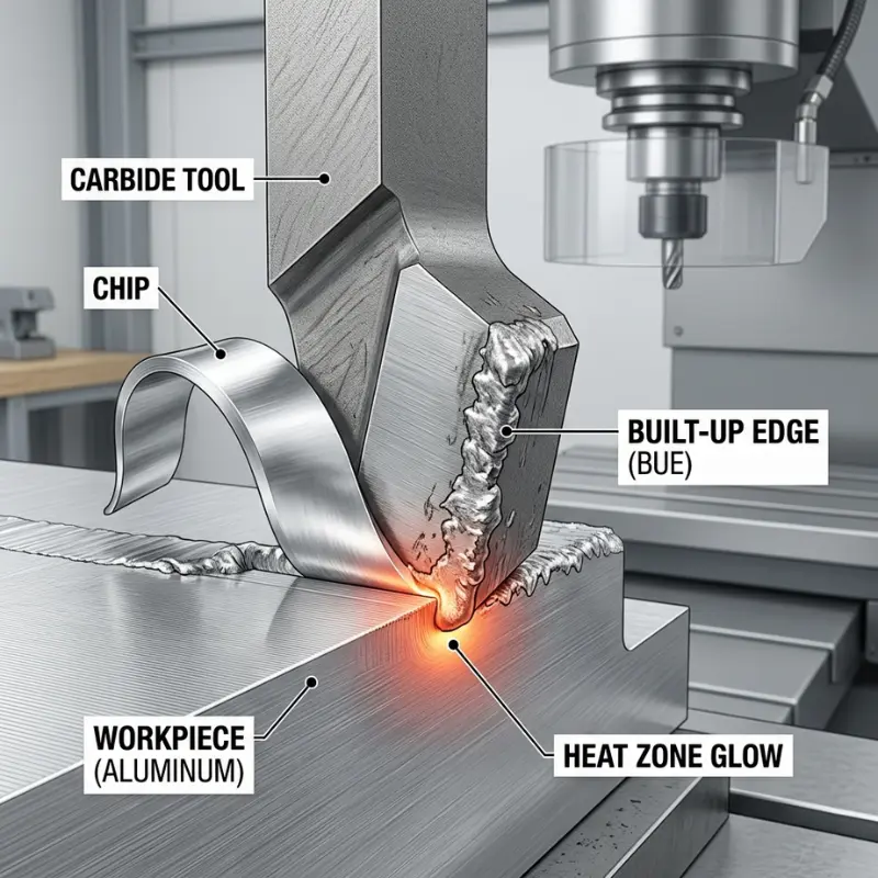
What Causes Built-Up Edge in Aluminum Machining?
BUE happens when aluminum welds itself to your cutting edge. Not a loose deposit, but a micro-weld. It is one of the most common causes of poor surface finish and dimensional drift when working with a CNC machining service.
What Is Built-Up Edge (BUE)?
The chip slides across the tool’s rake face under pressure and heat. Aluminum has a chemical affinity to carbide and high-speed steel.
At low cutting speeds, the chip stays in contact with the rake face long enough for a bond to form. That bonded material builds up. It grows until it becomes unstable, then breaks off. When it breaks, it tears the machined surface or chips the cutting edge.
Why BUE Happens?
The surface looks torn or smeared instead of clean. The marks are irregular. It looks like the material was pulled, not cut. Dimensionally, BUE is one of the main causes of aluminum surface finish problems.
The bond material changes the shape of your cutting edge. Your tool is now cutting with a different geometry than the one you chose. This causes dimensional drift. Parts at the beginning of a batch measure differently from parts at the end.
How to Prevent Built-Up Edge?
1. Maintain High Cutting Speeds
High cutting speed is the best way to fix problems. For most aluminum, you should keep your speed between 300 and 600 meters per minute. If you go slower than this, the metal will likely stick to your tool. If you go faster, the chips will touch the tool for a shorter time, which keeps the tool cleaner.
2. Select the Right Tool Coating and Finish
The coating on your tool is also important. Some coatings, like DLC, are very smooth and do not stick to aluminum. However, other coatings like TiN are bad for aluminum because they make the metal stick even more. It also helps to use tools with polished, shiny grooves. This allows the waste metal to slide out faster, so it does not rub against the tool.
3. Use Sharp Tool Geometry
Finally, use tools with a sharp positive angle. Most tools made for aluminum have an angle of 10 to 15 degrees. This shape helps the tool cut through the metal cleanly instead of pulling or pushing it.
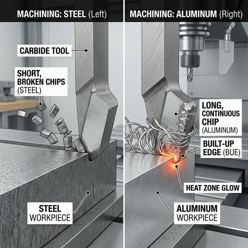
Why Aluminum Produces Long Chips in CNC Machining?
If we talk about aluminum vs steel machining, in steel, chips break into short pieces. In aluminum, chips form long continuous ribbons. Those ribbons wrap around the tool, pack into pockets, and get re-cut. Each re-cut scores your surface and accelerates tool wear.
Why aluminum chips are long and stringy?
Aluminum has low shear strength. The material shears continuously as the tool moves. There is no natural fracture point in the chip. It comes off as one long strand. This is the worst in 1000-series pure aluminum and in softer tempers of 6061. Even 7075 can produce long chips under certain cutting conditions, though it is generally more manageable.
Problems Caused by Poor Chip Removal
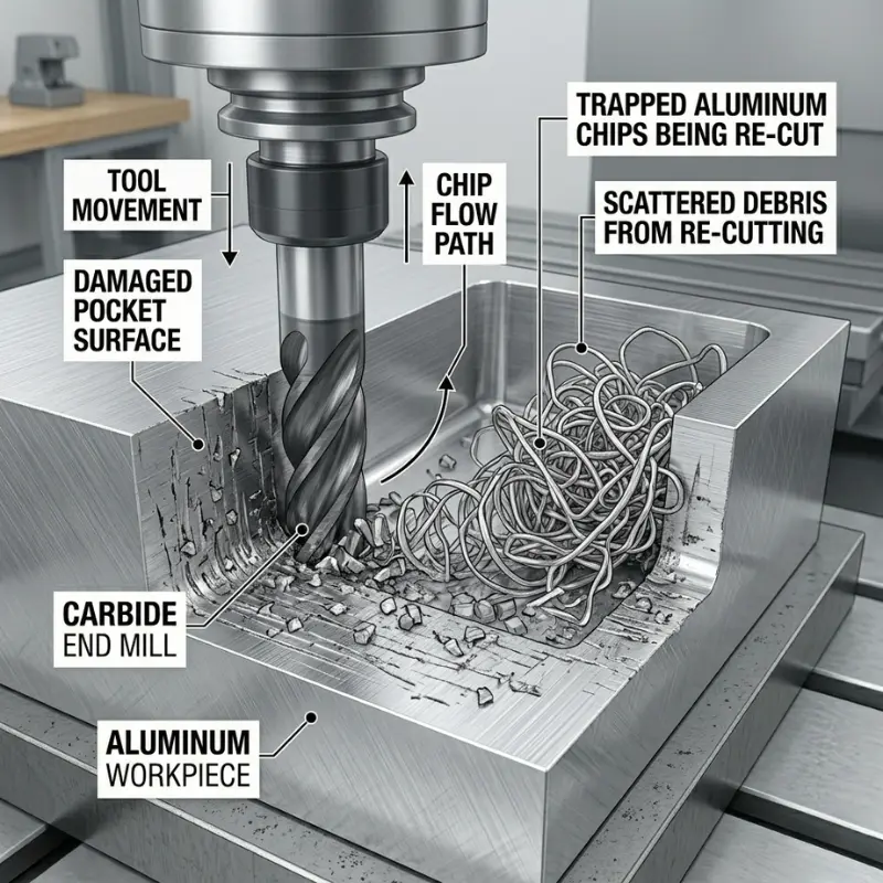
Chips that stay in the cutting zone get re-cut. Every pass through the cutting zone again damages the surface and adds heat. In deep pockets, chips have nowhere to go. They pack in and start welding to the walls. The surface ends up gouged. In drilling, long chips are worse — they jam inside the hole and can snap the drill entirely.
How to Improve Chip Control in Aluminum Machining
1. Select the Correct Flute Count
Use two-flute or three-flute end mills for aluminum. Four-flute and higher-flute tools leave less space between flutes for chip evacuation. Two flutes give each chip a clear exit path.
2. Utilize High-Helix Tool Geometry
High-helix tools — helix angle above 45 degrees — actively pull chips upward and out of the cutting zone as the tool spins. This is not a small improvement. On deep pockets, especially, the difference is significant.
3. Optimize Toolpaths and Coolant Direction
Adaptive clearing toolpaths keep radial engagement consistent. That produces a more uniform chip size, which is easier to evacuate. Coolant aimed directly into the cutting zone flushes chips out before they can re-enter.
Why Aluminum Warps After Machining?
Aluminum conducts heat well. Heat generated at the cutting zone moves into the part quickly. The part expands. If you are holding tight tolerances, that expansion is a real problem.
Thermal Expansion in Aluminum
Take a 200 mm aluminum part. A 10-degree rise in part temperature causes about 0.047 mm of growth. For general machining, that is fine. For aerospace tolerances at ±0.01 mm or tighter, that one temperature change breaks your spec. In actual cutting, temperature fluctuations are often much larger than 10 degrees.
Starting and stopping the coolant mid-operation makes this worse. Thermal cycling — heating and cooling repeatedly — can cause more dimensional movement than running dry. Apply coolant consistently or not at all in a given operation.
Residual Stress in Material
You finish a part. It measures correctly on the machine. An hour later, it has moved. This is a residual stress problem. Two things cause it. First, your clamps hold the part in a stressed position during cutting. Second, removing material changes how internal stresses in the raw stock are balanced. When the clamps release, those stresses redistribute, and the part deforms.
This is most common in 7075-T6 and 2024-T3. Both alloys carry significant internal stress from rolling or extrusion. Aerospace shops dealing with 7075 plate routinely do a stress-relief step between roughing and finishing. Without it, parts move.
How to Prevent Aluminum Warping?
- Split the job into roughing and finishing stages
- After roughing, let the part cool to room temperature before the finishing pass.
- Measure at a stable temperature. Use fixturing that supports the part without over-clamping
- Remove material in balanced passes — take from one side, then the other — rather than cutting all material from one side first.
Why Thin Walls and Deep Pockets Are Difficult to Machine
Aluminum is chosen for lightweight parts with thin walls and tight geometry. Those same features are where machining gets difficult. The material properties that make it lightweight also make it deflect, vibrate, and deform during cutting.
Thin Wall Deflection Problem
Milling a 1.5 mm aluminum wall pushes it sideways. The wall moves away from the tool. Less material is removed than planned. When the cut finishes and the force stops, the wall springs back. The result is a wall that is too thick, with a slight curve to it.
Reduce cutting forces. Use shallower depths of cut, sharper tools, and higher spindle speeds. Some shops fill thin-wall pockets with wax or low-temperature casting material before machining, then melt it out afterward. The fill supports the wall during cutting.
Deep Pocket Chatter Problem
Reaching the bottom of a deep pocket requires a long tool. Long tools vibrate at high speeds. That vibration — chatter — leaves a pattern of ridges on the surface. At 15,000 RPM, the harmonics in a long-reach tool can create surface marks that require re-machining to remove.
Keep tool stickout as short as possible. In deep operations, reduce cutting speed. Use a high axial depth of cut with low radial engagement — this approach reduces cutting forces while keeping material removal rate reasonable.
Fixturing Solutions for Complex Aluminum Parts
Over-clamping introduces stress that warps the part when you release it. Under-clamping lets the part move during cutting. For complex parts with thin sections, custom fixtures that contact the part at multiple points are necessary. Vacuum chucks work well for flat parts.
For complex profiles, fixtures machined to match the part shape distribute clamping force without concentrating stress.
6061 vs 7075 Aluminum Machinability
| Series | Principal Alloy | Type | Yield Strength (MPa) | Melting Range (°C) |
| 1000 | None (99% Pure) | Non-Heat | 30 – 165 | 643 – 657 |
| 2000 | Copper | Heat | 110 – 450 | 502 – 638 |
| 3000 | Manganese | Non-Heat | 40 – 250 | 629 – 654 |
| 4000 | Silicon | Non-Heat* | 100 – 400 | 527 – 632 |
| 5000 | Magnesium | Non-Heat | 40 – 350 | 568 – 652 |
| 6000 | Mg + Si | Heat | 55 – 350 | 582 – 652 |
| 7000 | Zinc | Heat | 230 – 570 | 477 – 635 |
| 8000 | Lithium/Other | Heat/Misc | Varies | 540 – 645 |
Ask any experienced machinist what aluminum is easy to machine and they will ask which alloy. The series you choose changes your tool selection, cutting speed, coolant strategy, and post-machining behavior. They are not interchangeable.
1000-Series Aluminum Machining Challenges
1100 aluminum is 99% pure. It cuts fast — up to SFM 1000. But it produces the worst chip control of any common aluminum grade. Chips are long, soft, and sticky. They weld to tools and surfaces very easily. Clamping pressure alone is enough to cause dimensional problems because the material is so soft. Machinists who try 1000-series for the first time are usually surprised that something so soft is so difficult to get a clean result from.
6061 vs 7075 Machinability Comparison
| Property | 6061 Aluminum | 7075 Aluminum |
| Primary Alloying Element | Magnesium & Silicon | Zinc |
| Tensile Strength (Ultimate) | ~310 MPa | ~570 MPa |
| Yield Strength | ~275 MPa | ~503 MPa |
| Melting Point | 582°C – 652°C | 477°C – 635°C |
| Thermal Conductivity | 167 W/m-K | 130 W/m-K |
| Hardness (Brinell) | 95 | 150 |
| Machinability Rating | Good (Approx. 50%) | Fair (Approx. 70-80%) |
6061-T6 Aluminum Machinability
6061-T6 is the most forgiving aluminum for CNC work. You can cut it at 4 to 5 times the speed you would use for 316 stainless steel. Chips are manageable. Tolerances are stable in T6 temper. It is predictable. If you are setting up a new aluminum process, 6061 is where to start.
7075-T6 Aluminum Machinability
7075-T6 is stronger — roughly twice the yield strength of 6061. It cuts more like steel. Tool wear is higher. It is much more sensitive to residual stress. Plate stock of 7075 carries significant internal stress from rolling.
When you remove material, that stress releases and the part moves. Shops that machine 7075 for aerospace applications almost always do a stress-relief step between roughing and finishing. Without it, the scrap rate goes up.
High-Silicon Aluminum Alloys and Tool Wear
Die-cast aluminum alloys with more than about 10% silicon contain hard free-silicon particles. These particles are abrasive. They wear cutting edges much faster than standard aluminum alloys. Regular carbide tools degrade quickly. For production runs on high-silicon alloys, polycrystalline diamond (PCD) tools are the correct choice. DLC coatings on carbide improve resistance but are not a full substitute for PCD on high volumes.
How Alloy Choice Affects Machining Cost
If you have design flexibility, choosing 6061 over 7075 for a non-structural part can cut machining time significantly and double tool life. Choosing 1100 or 5052 to save on material cost can increase finishing time enough to cost more overall. Talk to your machining supplier before you finalize the alloy. It is a decision that affects price, lead time, and part quality.
How to Solve Aluminum Machining Problems?
Every challenge above has a specific solution. The issue with machining aluminum is that applying those solutions correctly takes experience, proper equipment, and consistent process control. Here is what to look for in a CNC machining supplier for aluminum work.
BUE (Built-Up Edge)
This happens when aluminum sticks to the cutting tool. To fix this, make the tool move faster. Use a liquid (coolant) that makes the surface slippery. You can also use tools with a shiny, polished surface or a special “DLC” coating. These methods stop the metal from sticking.
Chip Control
Aluminum often creates long, curly pieces of waste called chips. These can scratch the part or break the tool. To fix this, use tools with two or three deep grooves to push the chips out quickly. You should also use strong water pressure to wash the chips away from the work area.
Warping
Aluminum changes shape easily when it gets hot or when it is cut. To keep the part straight, do not let the metal get too hot. Use a stress-relief step. It means letting the metal rest between the first rough cut and the final smooth cut. Also, make sure the tool moves in a steady, balanced way.
Best Tooling for Aluminum Machining
The baseline for aluminum: solid carbide end mills, 2 to 3 flutes, high-helix geometry, polished flutes. For high-silicon die-cast alloys, PCD inserts. For jobs where BUE has been a problem, DLC-coated tools. A shop running general-purpose 4-flute tools on all aluminum is not set up for the material.
Best Cutting Parameters for Aluminum
For 6061 and similar alloys: cutting speed 300 to 600 m/min, feed rate 0.1 to 0.3 mm/rev, spindle speed 8,000 to 20,000 RPM depending on tool diameter. These numbers shift based on machine condition, tool state, and part geometry. A supplier who cannot give you parameter logic specific to your alloy is guessing.
On coolant: a neat cutting oil or high-lubricity synthetic produces better surface finishing than standard water-soluble coolant. Lubricity matters more than cooling volume. Dry cutting aluminum in production is rarely the right call — adhesion risk is too high.
Questions to Ask a CNC Machining Supplier
-
Experience
Ask if they have experience with your specific alloy. 6061 and 7075 are not the same job.
-
Fixturing
Ask how they handle fixturing for thin-wall or complex parts.
-
Tool Management
Ask how they manage tool life across a batch — scheduled replacement based on part count, or running until quality drops.
-
Inspection Process
Ask about their inspection process. BUE damage and chip re-cutting often look fine until a part reaches assembly. In-process inspection catches those problems before they reach you.
When to Use Professional CNC Machining Services?
Tight Tolerance is Required
Use professional CNC machining services when your parts must be exact. This is important if a part needs to fit perfectly with other pieces or if you need very small measurements, such as ±0.1 mm.
Need High-Quality Surface Finishing
Choose professionals for parts that must look perfect or be clear, like lenses and light panels. They can control the finish and prevent the material from breaking under pressure.
Multi Axis Machining Requirements
Some designs have many curves or difficult angles. Professionals use advanced machines like 4-axis or 5-axis tools to cut shapes that simple machines cannot make.
Functional Prototypes and Small Batches
This service is great for making a few parts to test your design. It is often cheaper than making a permanent mold when you only need a small number of items.
Sensitive Materials
Some plastics, like acrylic, can crack or melt easily. Professionals know how to control the heat and speed so the material stays strong and looks good.
Summary
Aluminum is not so simple to machine because of four reasons: low melting point, high ductility, high thermal expansion, and low stiffness. These cause six recurring problems:
- BUE
- Chip control
- Dimensional drift
- Aluminum warping after machining
- Thin-wall deflection
- and alloy-specific behavior.
Each has a known fix. If you know which property is causing your problem, you know where to start.
At Ydrapid, we make sure your parts are the exact size you need, even down to ±0.01 mm, on the very first try. We work with strong metals like 7075-T6 for airplanes and 6061-T6 for fast production. You can upload your design files to get a full report on your project within 24 hours.
Contact us now, and get an instant non-obligatory quote for your project.

FAQs
1: Is aluminum easy or hard to machine?
Aluminum cuts fast. Many people think this means it is easy. But fast cutting is not the same as easy machining. Aluminum sticks to tools, produces long, messy chips, and warps after cutting. The difficulty depends on the alloy, too. 6061 is forgiving. 7075 and high-silicon alloys are much harder to work with.
What causes aluminum built-up edges?
Aluminum has a low melting point of 660°C. When the tool cuts the metal, friction creates heat. This heat softens the aluminum just enough that it sticks to the cutting edge. It does not break away cleanly as steel chips do. Over time, this stuck material builds up on the tool. When it finally breaks off, it tears the surface of your part.
Why does aluminum warp after machining?
Your clamps hold the part in position during cutting. This creates stress inside the metal. When you remove the clamps, that stress has nowhere to go. The part bends slightly to release it. This problem is worse with 7075 and 2024 alloys. Both carry internal stress from the rolling process before you even start cutting.
Which is easier to machine, 6061 or 7075?
6061 is much easier. You can cut it at 4 to 5 times the speed of stainless steel. The chips are manageable, and the part holds its dimensions well. 7075 is stronger, but it behaves more like steel under the tool. Tool wear is higher. The part is also more likely to warp after roughing because 7075 plate carries more internal stress.