Molybdenum entails excellent thermal stability. Therefore, it is used in parts that must hold strength at elevated temperatures. It is primarily used in aerospace hardware, furnace components, and thermal tooling where standard materials fail. These applications demand high stability. So, machining molybdenum is not straightforward.
Molybdenum behaves differently from common metals like steel and aluminium during cutting. It generally remains high cutting force, and heat builds up at the tool edge rather than dissipating into the material.
As a result, tool wear and edge chipping occur if the process is not controlled, especially when working with a CNC machining service under high-load and high-temperature conditions. Thus, for precisely machining molybdenum, you need a stable approach to obtain optimal outcomes.
Keep on reading as this article explains:
- Molybdenum behavior during CNC machining and cutting
- Typical challenges and their preventive measures
- Tool selection and cutting parameters for stable machining
- Design considerations
What Is Molybdenum CNC Machining & How Does It Work?
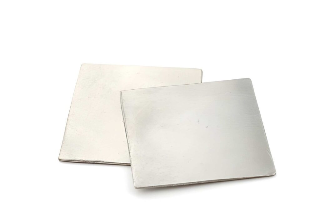
Molybdenum CNC machining involves removing material from blocks, rods, and sheets using milling, drilling, and cutting. Its parts can withstand high temperatures and high mechanical loads.
However, the material does not machine like standard materials such as aluminium, steel and titanium. The process depends on controlled cutting conditions and stable machine setup rather than aggressive material removal.
Workpiece Setup and Clamping
- Use a rigid fixture that fully supports the workpiece
- Distribute clamping force evenly to avoid part distortion
- Clean fixture and part contact surfaces before clamping
- Keep the tool overhang as short as possible for stability
- Verify alignment between the workpiece datum and machine axis before cutting
Rough Machining Stage
- Use this stage to remove excess material from the blank
- Keep the cutting depth controlled to avoid a sudden tool load increase
- Allow some material stock for later correction in finishing
- Watch for vibration signs during deeper cuts
Semi-Finishing Stage
- Reduce cutting load compared to the roughing operation
- Bring geometry closer to final dimensions
- Stabilize roundness and straightness before the final pass
- Remove irregular tool marks from the previous stage
- Check intermediate measurements before moving forward
Finish Machining Stage
- Apply light cutting depth for final sizing
- Maintain a steady feed to avoid surface variation
- Use measured offset adjustment instead of fixed values
- Complete the pass in one continuous operation when possible
Heat Management During Cutting
- Keep coolant flow directed at the cutting zone
- Allow temperature to stabilize before final measurement
- Avoid long, dry contact between the tool and the workpiece
- Reduce heat buildup during long cutting cycles
- Consider thermal expansion before setting the final tolerance
Tool Wear and Process Stability
- Inspect tool condition after each machining cycle
- Replace tools once edge wear begins affecting the size
- Monitor gradual size shift during repeated runs
- Adjust offsets based on actual measured parts
Comparing Molybdenum with Common Engineering Metals
This table compares molybdenum, steel, aluminum, titanium, and copper to help you decide which material is suitable for your part applications.
| Engineering factor | Molybdenum (Mo) | Carbon Steel (AISI 1045) | Titanium (Grade 5 Ti-6Al-4V) | Aluminum (6061-T6) | Copper (C110) |
| Melting point | 2623°C | ~1450°C | ~1660°C | ~660°C | ~1085°C |
| Density | 10.28 g/cm³ | 7.85 g/cm³ | 4.43 g/cm³ | 2.70 g/cm³ | 8.96 g/cm³ |
| Thermal conductivity | ~138 W/m·K | ~50 W/m·K | ~7 W/m·K | ~167 W/m·K | ~390 W/m·K |
| Thermal expansion | ~4.8 µm/m·K | ~12 µm/m·K | ~8.6 µm/m·K | ~23 µm/m·K | ~16.5 µm/m·K |
| Strength at high temperature | Retains strength above 1000°C | Drops significantly above 500°C | Moderate retention up to mid-range | Rapid strength loss above 200°C | Low structural strength at heat |
| Machining behavior | Difficult, high tool wear | Moderate machinability | Difficult, work hardening | Easy machining | Easy but gummy cutting |
CNC Machining Molybdenum Techniques and Practical Considerations
Molybdenum CNC machining depends on stable cutting conditions, rigid setups, and controlled tool engagement.
Rough Machining Strategy for Molybdenum Components

Rough machining is used when parts start from solid molybdenum billets or forged stock. It is common in furnace blocks, aerospace structural mounts, and high-temperature support components, where large material removal is required before precision work.
- Use when stock removal exceeds 1.0 mm per side.
- Keep depth of cut in the range of 0.5 to 2.0 mm, depending on tool rigidity.y
- Maintain cutting speeds around 20 to 60 m/min with carbide tools
- Avoid excessive spindle load since tool edge failure increases sharply above stable cutting limits
- Use a steady chip load instead of aggressive depth increase
- Leave 0.2 to 0.5 mm allowance for finishing passes
CNC Molybdenum Machining Techniques
Molybdenum CNC machining involves milling, turning, and drilling. The intended choice of technique is based on part geometry, tolerance, and material removal requirements.
CNC Milling of Molybdenum Components
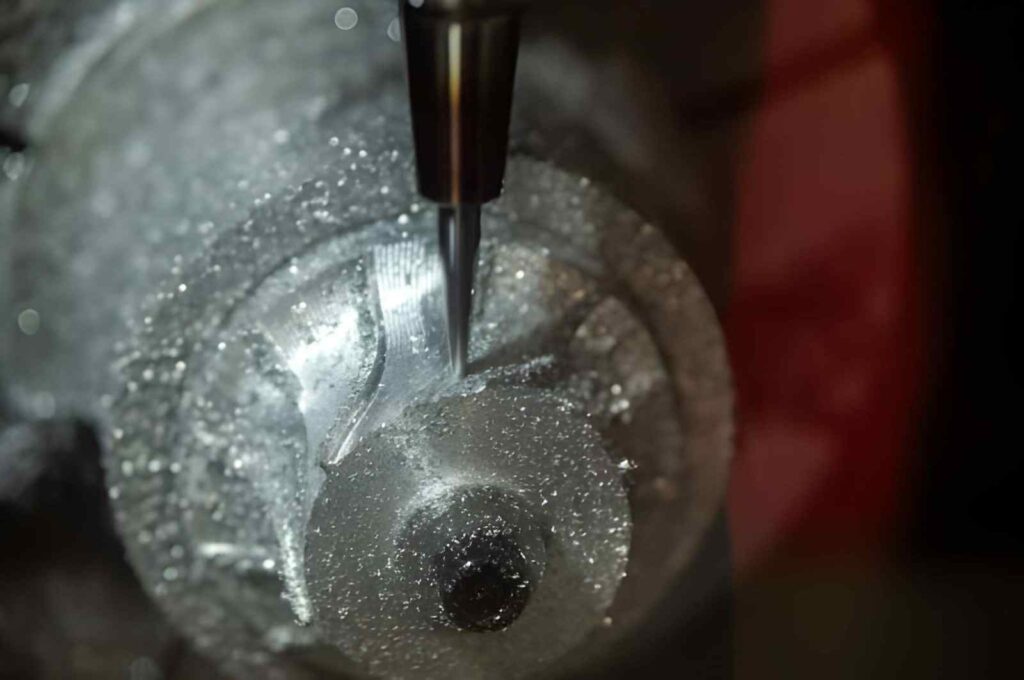
CNC milling is normally used for flat surfaces, pockets, and structural parts such as furnace plates, aerospace brackets, and precision mounting blocks. It works best with carbide tools and controlled engagement rather than full-width cutting.
Shallow depth of cut helps maintain stability and prevents excessive cutting force buildup. In most cases, the depth is kept around 0.2 to 1.5 mm, depending on part rigidity and tool diameter. However, there are challenges in milling molybdenum with vibration sensitivity and frequent tool wear.
Even a small tool deflection can affect the surface finish and increase wear at corner transitions. Therefore, consistent feed rate and smooth toolpath transitions are critical.
- Preferred for multi-surface and complex geometry parts
- Uses carbide end mills with controlled radial engagement
- Depth of cut is typically kept between 0.2 and 1.5 mm, depending on rigidity
- Feed is adjusted to avoid sudden tool load spikes
- Tool wear increases quickly at corner transitions
- Surface finish depends strongly on vibration control
Molybdenum CNC Turning
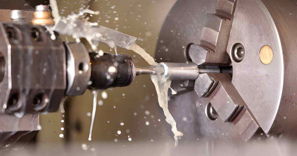
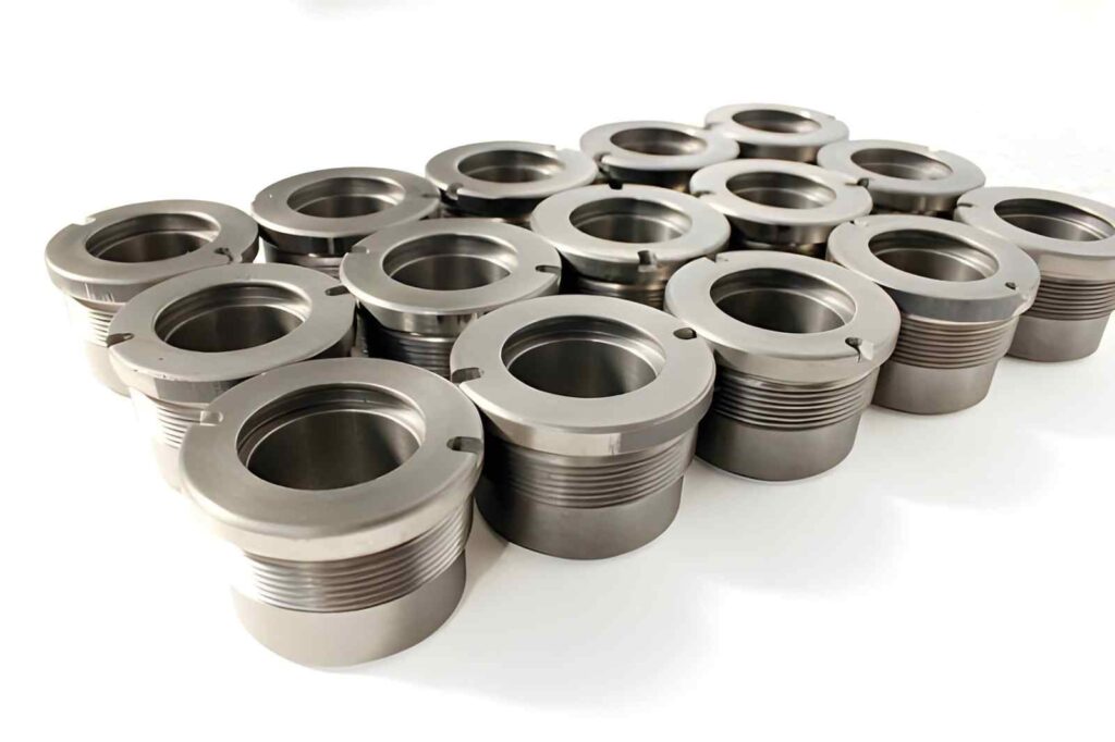
CNC turning is used for cylindrical parts like shafts, spacers, and high-temperature rotating components. In molybdenum, turning is a heat-intensive process. This is because the cutting zone remains in continuous contact with the tool.
To mitigate this, the cutting speed is kept relatively low, while the feed rate is maintained steady to prevent rubbing instead of cutting. Carbide inserts with strong edge geometry are typically used to resist premature wear.
- Applied for external and internal cylindrical features
- Cutting speed is normally kept low due to heat concentration
- Small depth of cut improves tool life and surface stability
- Rigid tool holding is critical to avoid chatter
- Insert wear appears quickly at the cutting edge during long runs
Molybdenum CNC Drilling
CNC drilling is used for creating holes in housings, fixtures, and alignment components before finishing operations. There are two primary types of drilling.
- Pilot drilling is often used before final sizing to reduce load on the main drill.
- Peck drilling is also important because it helps break chips and control heat buildup inside the hole.
Without proper chip evacuation, friction increases rapidly, which can lead to tool failure or hole inaccuracy.
- Pilot drilling is often required before final sizing
- High hardness increases tool wear at the entry point
- Peck drilling helps manage chip evacuation and heat
- Drill rigidity affects hole straightness and roundness
High Speed CNC Strategy for Thin-Wall Molybdenum Parts
High-speed machining is used only in controlled conditions where machine rigidity and tool condition are verified. It is mainly applied in thin-wall aerospace components and thermal management plates.
Here are the typical considerations for high-speed CNC machining.
- Maintain RPM within a stable range of 3000 to 8000, depending on tool diameter.
- Use light radial engagement below 0.2 mm to prevent deflection
- Apply sharp, coated carbide tools to reduce heat concentration at the cutting edge
- Avoid long tool overhang above a 4:1 length-to-diameter ratio
- Monitor vibration continuously since instability appears quickly in molybdenum
Deep Cavity CNC Machining for Complex Molybdenum Parts
Deep cavity machining is used in furnace chambers, die inserts, and sealed high-temperature housings. The main challenge is chip evacuation and heat accumulation inside confined spaces.
- Reduce step-down to 0.2 to 0.8 mm, depending on cavity depth
- Maintain consistent coolant flow above 6 to 10 L/min for heat control
- Avoid chip accumulation since it increases tool wear and surface damage
- Use rigid carbide or damped tools for reach beyond 5× diameter
- Plan tool paths to minimize re-entry cuts and thermal cycling
What are the Common Challenges Encountered During Molybdenum Machining
Molybdenum CNC machining generates high tool stress because the material resists cutting and concentrates heat at the cutting edge.
High Cutting Force and Tool Wear
- Cutting forces remain high even when the depth of cut is reduced during machining operations.
- Tool flank wear develops faster compared to common engineering metals such as steel or aluminium.
- Cutting-edge chipping occurs during sudden load changes at corners and entry points.
- Small changes in feed rate directly affect tool life and surface stability in production.
- Tool condition requires regular inspection during batch machining to avoid sudden failure.
Necessary Take-Ups
- Use radial engagement around 10–20% of the tool diameter to limit load concentration.
- Keep feed per tooth in a low stable range, typically 0.01 to 0.05 mm/tooth for carbide tools.
- Maintain a short tool overhang within 3× tool diameter or less to reduce bending stress.
Heat Concentration at Cutting Zone
- Heat remains concentrated at the cutting interface instead of spreading into the material.
- Tool temperature continues to rise during extended machining cycles.
- Dimensional accuracy changes when thermal conditions are not controlled properly.
- Surface finish becomes inconsistent when heat buildup increases at the cutting zone.
- Coolant flow plays an important role in maintaining stable cutting conditions.
Necessary Takeups:
- Apply flood coolant or high-pressure coolant in the range of 20 to 70 bar for stable heat removal.
- Use moderate cutting speeds, typically 30 to 80 m/min for carbide tooling in molybdenum machining.
- Avoid dwell time completely at entry or corner transitions to prevent localised heat buildup.
Vibration and Stability Issues
- Tool deflection increases when the tool overhang becomes longer than the recommended limits.
- Thin-wall sections show instability during finishing operations under cutting load.
- Fixture rigidity directly affects surface finish and dimensional consistency.
- Uneven clamping pressure causes measurable part distortion during machining.
- Chatter develops when cutting forces are not balanced with machine rigidity.
Necessary Take-Ups
- Limit tool overhang to below 3× diameter, preferably closer to 2× for finishing operations
- Use depth of cut in finishing range of 0.1 to 0.5 mm per pass for stability and control.
Surface Finishing Techniques for Molybdenum
Surface finishing in molybdenum machining includes both mechanical and surface treatment processes. The selection depends on part function, operating temperature, wear condition, and surface contact requirements. In production environments, finishing is not applied for appearance, but for stability, performance, and service life in real operating conditions.
Mechanical Polishing for Functional Surface Smoothing
Engineers usually employ it for machined surfaces that require better contact quality in assembly, especially in sealing faces and precision mating parts.
When to choose it?
- Used when flatness and smooth contact are critical in assembly performance
- Common in sealing components, vacuum parts, and precision mechanical interfaces
Electropolishing for Uniform Surface Improvement
Electropolishing is used when complex geometries require uniform surface quality without affecting dimensional accuracy. It is often applied to components with intricate shapes where tool access is limited
When to employ it?
- Used to reduce micro-roughness after CNC machining operations
- Common in semiconductor equipment and controlled environment components
PVD Coating for Wear and Friction Control
PVD coatings are particularly applied to improve surface hardness and reduce friction during operation.
When to choose it?
- Used when components operate under load and moderate thermal exposure
- Used when molybdenum parts are exposed to sliding contact, wear, or repeated mechanical load.
- Common in aerospace assemblies and high-contact mechanical systems
Diffusion Coating for High Temperature Protection
Diffusion coating is used when parts operate in extreme heat environments where oxidation resistance is required.
- Applied to improve surface stability at elevated temperatures
- Used in furnace systems and high-temperature tooling applications
- Common in thermal processing equipment and heat exposure components
Surface Cleaning and Passivation for Process Stability
Passivation is used before assembly, coating, or service to ensure a clean and stable surface condition. It is commonly found in vacuum systems, aerospace parts, and semiconductor components
When to Choose it?
- Choose before coating or bonding operations
- Apply when surface contamination affects performance
Considerations for CNC Molybdenum Machining
Molybdenum machining depends heavily on process stability. The material generates high cutting resistance and keeps heat concentrated at the tool edge.
Tool Selection and Rigidity Control
Tool stiffness and edge condition decide whether the cut stays stable or starts breaking down.
- Use solid carbide tools because they resist edge collapse under load
- Keep the tool overhang within the shortest possible reach for the operation
- Use sharp cutting geometry since blunt edges increase heat quickly
- Check the holder runout since even a small deviation affects bore and surface accuracy
Cutting Load Management
- Maintain cutting speed between 20 and 80 m/min. It depends on the tool diameter and setup.
- Keep the feed steady. Because fluctuation often causes edge chipping at entry points
- Use controlled depth of cut instead of increasing engagement for productivity.
- Avoid sudden parameter changes during continuous tool engagement
Heat Behaviour and Thermal Drift
Heat stays near the cutting zone and directly affects dimensional stability.
- Apply continuous coolant flow to control tool interface temperature
- Avoid dry cutting since it increases edge wear within short cycles
- Allow thermal stabilization before final inspection on tight-tolerance parts
- Expect size variation during long runs due to thermal expansion, not machining error
Fixture Rigidity and Vibration Control
The setup strength determines whether molybdenum cuts cleanly or develops chatter.
- Use rigid fixturing since any movement reflects directly in the surface finish.
- Apply an even clamping force to prevent part distortion during cutting
- Reduce tool reach since long overhang increases vibration risk
- Treat chatter as a setup issue first, not a tool issue
Contact YDrapid for Design Guideline & Custom Part Machining Solutions
Contact Ydrapid for design support and custom CNC machining solutions. If your project involves tight tolerances or complex geometry, early input helps avoid machining issues later in production.
At Ydrapid, our engineers support machining of critical features and tolerance-critical parts where fit and stability matter in assembly. Process planning is done based on real material behaviour and part geometry.
You can upload your CAD file for a technical review. The engineering team checks manufacturability, highlights risk areas, and suggests improvements before production starts.
The review also includes critical dimension checks, fit evaluation, and lead time estimation based on actual machining conditions. Both prototypes and low-volume production are supported without minimum order limits.
Start with a design review and get a quote based on your part data.

FAQ’s
Why is molybdenum difficult to CNC machine?
Molybdenum produces a high cutting force and keeps heat at the tool edge. This leads to faster tool wear and makes surface control harder compared to common metals.
What tools work best for molybdenum machining?
Solid carbide tools with sharp cutting edges perform better. Short tool overhang and rigid holders help control vibration and improve surface finish.
How is heat controlled during machining?
Continuous coolant flow is used to control heat at the cutting zone. Thermal stabilization is also important before final inspection.
Why does tool wear happen quickly?
Tool wear increases because of high cutting resistance and concentrated heat. Poor rigidity or unstable feed makes wear even faster.
How much does machining molybdenum cost?
Machining cost depends on machining time and tool wear. Molybdenum is harder on tools, so tools need more frequent replacement. Complex shapes, tight tolerances, and deep cuts also increase cost because machining takes longer and needs more control.