Boring machining is a precision cutting process used to enlarge and improve the accuracy of an existing hole in a workpiece. It is usually performed after drilling when the initial hole does not meet the required diameter, alignment, or surface finish needed for final assembly. The process helps achieve tighter tolerances and better geometric accuracy compared to drilling, typically improving from around ±0.05 to 0.10 mm in drilling to about ±0.005 to 0.01 mm in precision boring operations.
In contemporary part manufacturing, boring machining is widely used for refining internal diameters in components such as housings, shafts, and bearing seats. It ensures proper fit between mating parts, improves concentricity, and gives a smoother internal surface for functional performance.
This article explains:
- How CNC boring works
- How it differs from reaming and drilling
- Common boring types
- How does it improve part tolerance
- Design considerations for optimal boring outcomes
What Is Boring Machining?
As mentioned before, boring machining is a process often used to enlarge and true a pre-drilled hole. It is applied when the hole must meet tight requirements for diameter, concentricity, and alignment with other features. It is useful for
- It helps eliminate dimensional error and brings the hole diameter within +/- 0.01 mm tolerance
- Improving concentricity and reducing runout in rotating components
- Maintaining the alignment with the datums, especially for bearing bores
- Achieving the cylindricity and roundness compared to drilled holes, and surface finish around Ra 0.8 to 1.6 µm for functional fits
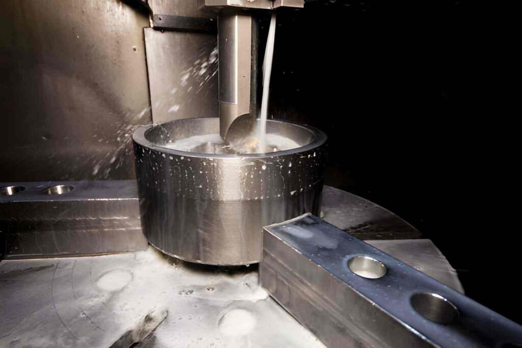
CNC Boring Machining Process Steps
Here are the commonest steps involved in boring CNC machining:
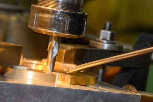
Hole Preparation: A hole is first created by drilling, casting, and pre-machining. Normally, it leaves about 0.2 to 1.0 mm stock per side for boring to remove and correct size and alignment.
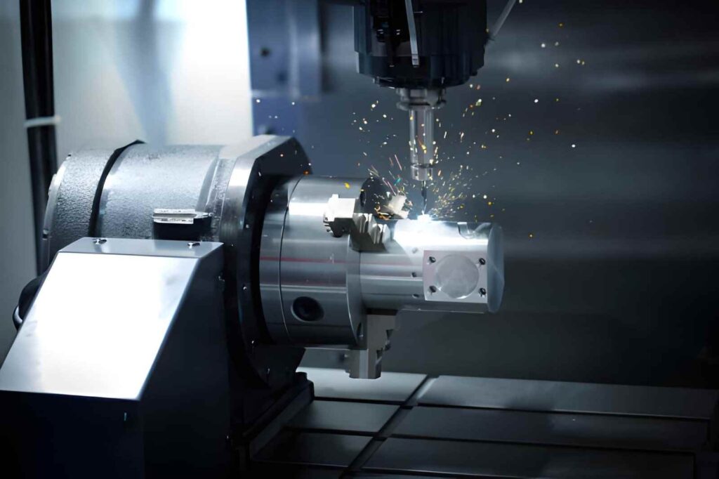
Tool Selection and Setup: The appropriate boring tool is selected depending on the hole size and depth. Examples are solid carbide boring bars, steel boring bars, and damped boring bars to use in deep holes. The diameter of the bars must be as large as possible, and overhang is normally maintained at a ratio of 3:1 to 6:1 to minimize deflection.
Workpiece Location: The part is fixed in place and oriented in such a way that the axis of the hole aligns with the spindle. The tool tip runout is normally kept under 0.005 to 0.01 mm to maintain the accuracy.
Rough Boring Pass: The tool will be used to remove more material and has a depth of cut of between 0.3 and 1.0 mm per side, and increased feed rates. This is done to correct the significant deviation of holes and also to prepare a smooth surface.
Semi-finish Bore: A moderate cut of 0.05 to 0.2 mm per side on each side is made to enhance roundness and reduce cutting load before final sizing.
Final Boring Pass: The final diameter and finish are obtained by a light cut of 0.01 to 0.03 mm/side. The feed rate is adjusted to low, and a constant RPM is maintained to avoid vibration.
Tool Offset Adjustment: Final hole dimension is governed with small steps of tool offset changes, typically between 0.002 and 0.1 mm, depending on measured values.
Measurement and control: Bear size is checked by dial bore gauges or internal micrometers at different depths to verify size, roundness, and straightness.
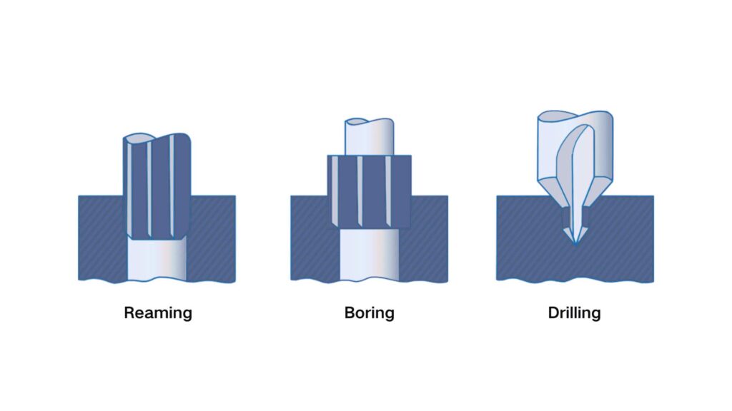
What Is the Difference between Drilling Vs Boring Vs Reaming?
Drilling
Drilling is the starting point for making a hole. It uses a rotating twist drill moving along the spindle axis (Z-axis) to cut directly into the solid material. Its main purpose is to create a basic hole position and approximate diameter for later operations. It allows you to achieve typical tolerance around ±0.05 to 0.10 mm. On the application side, drilling produces rough internal surfaces.
Reaming
Reaming is used after drilling when the hole is already closed to the required size. A multi-flute reamer is used through the existing hole and removes a small amount of material to improve accuracy and surface quality. Usually, it applies to pre-drilled holes with a small stock removal of around (0.1 to 0.3mm).
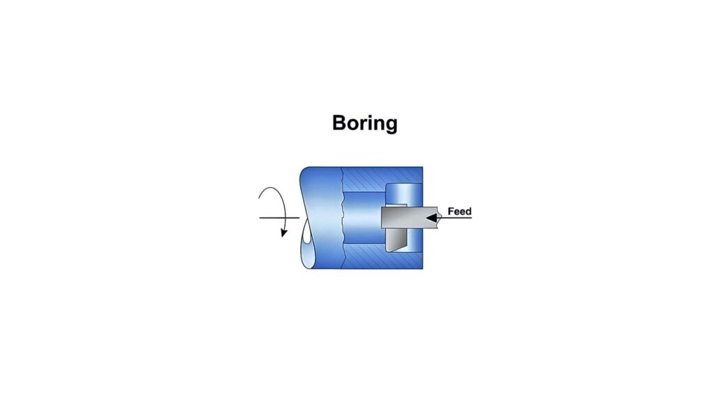
Boring
Boring is a precision CNC machining process that is used to enlarge and refine an existing hole. It uses a single-point cutting tool mounted on a rigid boring bar. The tool removes the material along the spindle axis (Z-axis) with a controlled offset for hole diameter adjustment.
Unlike drilling and reaming, boring can meticulously correct the hole axis errors and improve geometry across the full depth of a bore. It helps achieve a typical tolerance around ±0.005 – 0.01 mm in stable setups. Primarily, it is applied to bearing seats, housings, and alignment features.
The table below includes points of difference between boring, drilling, and reaming techniques.
Table 01: Drilling vs Reaming vs Boring
| Process | Typical Tolerance | What It Controls | Surface Finish | Practical Use |
| Drilling | ±0.05 to 0.20 mm | Only creates a hole, with low control over size and position | Ra 3.2 to 6.3 µm | Starting holes quickly before finishing |
| Reaming | ±0.01 to 0.02 mm | Improves size but follows the existing hole path | Ra 1.6 to 3.2 µm | Finishing holes where the position is already correct |
| Boring | ±0.005 to 0.01 mm | Controls size, alignment, and concentricity | Ra 0.8 to 1.6 µm | Finalizing holes for bearings and precision fits |
Why Boring Is Preferred Over Other Techniques for Precision Hole Control
Boring is used when a hole must meet functional requirements during assembly. It corrects errors left after drilling and helps achieve the feature within controlled limits.
- Hole Size Control (Tolerance): Bore size is adjusted using tool offsets instead of changing tools. This allows fine control to reach ±0.005 – 0.01 mm for bearing seats and shaft fits. It is used when standard drill sizes cannot meet fit requirements.
- Hole Geometry (Roundness and Straightness): Drilling often leaves a taper and a slight oval shape due to tool movement. While boring removes this by cutting along the spindle axis.
- Hole Alignment (Concentricity and Position): CNC Boring follows the machine axis rather than the drilled path. This allows correction of misaligned holes, especially in parts with multiple bores.
Internal Surface Condition: Boring produces a stable cut with less vibration compared to drilling. Therefore, it improves surface finish to around Ra 0.8 to 1.6 µm.
Common Types of CNC Boring Operations
Boring involves various approaches, and suitable operations are selected based on hole geometry, access, and tolerance requirements.
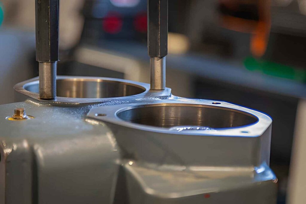
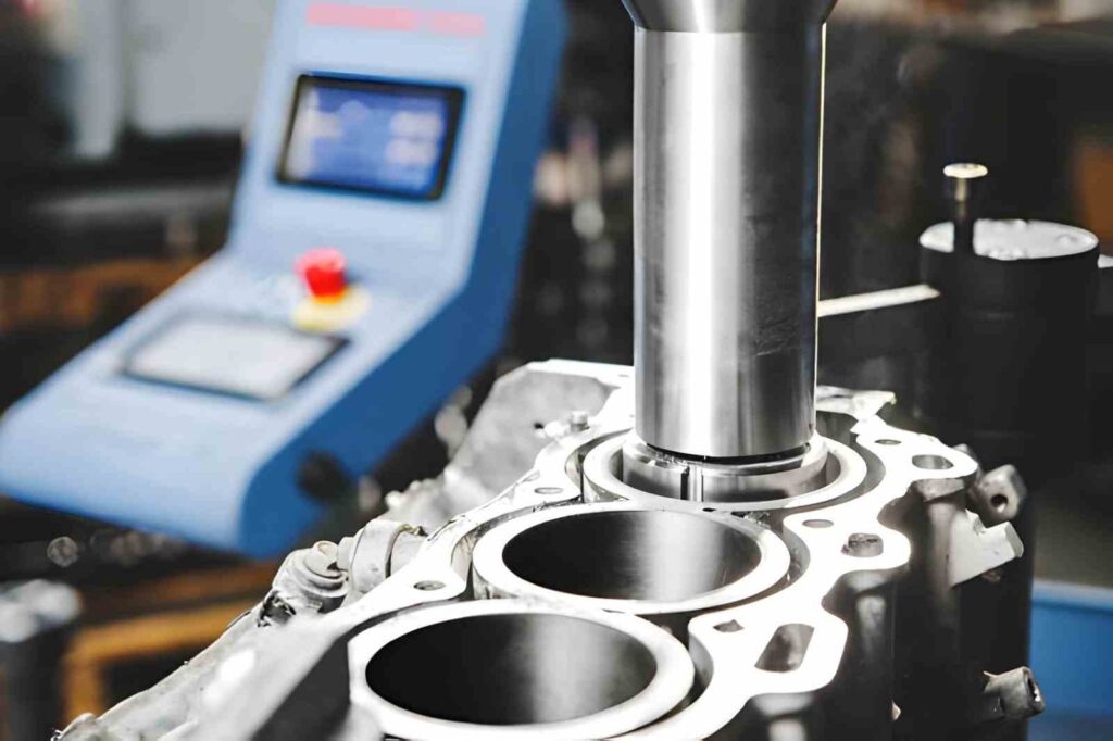
Line Boring
- It is used when multiple bores must remain aligned on a common axis
- Applied in housings where bearing seats must match across faces
- A single setup reduces positional error between bores
- It requires rigid fixturing to maintain alignment within +/- 0.01 to 0.02 mm
Back Boring
- Back boring is used to machine internal features located behind a surface
- The tool passes through the hole and cuts on the reverse side
- Applied for counterbores and internal steps not reachable from the front
- The tool expansion mechanism must remain stable to maintain size control
Finish Boring (Precision Boring)
- This type of boring is used for final sizing after rough machining and drilling.
- It removes a small allowance (0.1 to 0.3 mm) to achieve a tight tolerance
- Controls diameter within +/- 0.005 to 0.01 mm for precision fits
- It improves roundness and surface finish for bearing and sliding applications
Rough Boring
- Rough boring is used to enlarge holes before final finishing
- It removes bulk material with higher feed and depth of cut
- Leaves uniform stock for the finishing pass
Deep Hole Boring
- It is used when the hole depth exceeds 5× diameter
- Long tool overhang increases deflection risk
- It requires controlled feed and stable cutting conditions
- Chip evacuation must be managed to avoid surface damage and heat buildup
Comparative Analysis
The table gives a simple summary of each type to help you choose the right one for your part.
Table 02: Types of boring operations
| Boring Type | Feature Condition | Typical Use Case | Design Consideration |
| Line Boring | Multiple bores on the same axis | Gear housings, bearing blocks | Requires a single datum setup to maintain concentricity within ±0.01 to 0.02 mm |
| Back Boring | Internal backside features | Counterbores, internal shoulders | The tool must pass through the hole and expand, limited by access and diameter |
| Finish Boring | Final size and geometry control | Bearing seats, precision holes | Removes 0.1 to 0.3 mm allowance to achieve ±0.005 to 0.01 mm tolerance |
| Rough Boring | Pre-finishing material removal | Cast or drilled holes | Higher feed and depth, leaves uniform stock for finishing pass |
| Deep Hole Boring | High depth-to-diameter ratio (>5:1) | Shafts, hydraulic cylinders | Tool deflection and chip evacuation must be controlled for straightness |
How to Control Tolerance, Roundness, and Concentricity in Machined Bore Parts
Boring accuracy often depends on how stable the setup and cutting conditions are. Based on our experience, size errors and alignment issues come from tool deflection, heat, or poor referencing.
Setup and Datum Control
- If the part is not clamped evenly, the bore shifts during cutting
- Changing the setup between operations causes a mismatch in bore alignment
- Referencing from a non-critical surface leads to position error
Boring Bar Rigidity
- Long overhang increases deflection and tends to result in tapered bores
- Small-diameter bars can reduce stiffness in deep holes
- Vibration marks appear when the bar is not rigid enough
Cutting Load and Tool Behavior
- High depth of cut pushes the tool away, causing oversize diameter
- Low feed causes rubbing, which affects surface finish
- Worn inserts lead to inconsistent bore size across parts
Heat and Size Variation
- Heat buildup expands the material during machining
- Bore size may reduce after cooling if heat is not controlled
- Dry cutting in deep bores increases temperature quickly
- Coolant helps maintain a stable size during finishing
Material Response During Cutting
- Aluminum may expand during cutting and shrink after cooling
- Stainless steel builds heat and affects tool life
- Thin sections around the bore may move under the cutting force
- Leaving uniform stock before finishing reduces distortion
What are the Materials Suitable for CNC Boring
Boring stability, surface finish, and size control are directly affected by the behavior of the materials. Certain materials are easy to bore, whereas others pose a problem, such as deflection, overheating, and low-quality surfaces.
Aluminum Alloys (6061, 7075, 2024, 5052, 6063)
- Aluminum is relatively easy to machine with low cutting force. So, it reduces tool deflection.
- It also produces a stable bore size when proper cutting parameters are used.
- Heat buildup can cause temporary expansion during cutting
- However, it is not ideal for tight fits unless the temperature is controlled
Mild and Alloy Steels (1018, 1045, 4140, 4340, 8620)
- Steel provides good rigidity during cutting. So, it helps maintain bore geometry
- Generally, a higher cutting force increases tool wear compared to aluminum
- Thus, it requires proper coolant to manage heat and tool life
Stainless Steel (303, 304, 316, 410, 420)
- Stainless steels help maintain strength and shape under load. These are suitable for functional bores.
- Work hardening occurs if the feed is too low, affecting the surface finish
- Generates more heat, which reduces tool life
- More difficult to control compared to standard steels
Cast Iron (Gray Iron, Ductile Iron, Malleable Iron, Alloy Cast Iron)
- These materials have excellent damping properties and reduce vibration during boring
- Produces a consistent surface finish without built-up edge
- Brittle structure can cause edge chipping in some cases
Engineering Plastics (POM, PEEK, PTFE)
- Low cutting force reduces tool wear and allows smooth cutting
- Material can deform under clamping or cutting pressure
- Heat buildup may cause dimensional change during machining
- Harder to maintain a tight tolerance compared to metals
Design Considerations for CNC Boring Operations
Boring results depend on a few key decisions during setup and machining. These decisions affect size control, alignment, and surface quality.
Select the Right Boring Method
The choice between rough and finished boring should match the requirement. Rough boring is used when more than 0.3 mm of material needs removal. Finish boring is used when the final size and fit are required. Skipping roughing and going directly to finishing often leads to tool load variation and poor accuracy.
Match Tool Size to Bore Geometry
Tool diameter and length should match the bore size and depth. Using a small bar in a large bore reduces rigidity and affects size control. For deep bores, a larger diameter bar with minimum overhang gives better stability and consistent results.
Plan Stock Allowance Before Finishing
Material left after roughing must be uniform around the bore. Uneven stock causes the tool to cut more on one side, leading to size variation. Maintaining a consistent allowance of around 0.1 to 0.3 mm helps retain stable cutting during finishing.
Control Entry and Exit of the Tool
Tool entry into the bore should be smooth to avoid marks at the start of the cut. Sudden engagement can damage the surface and affect roundness. Similarly, controlled exit prevents taper or edge damage at the bore opening.
Check Bore During Machining
Measuring the bore after roughing helps confirm if enough material is left for finishing. Final measurement after boring ensures the size is within tolerance. For critical fits, checking during machining reduces the risk of scrap.
When CNC Boring Is Not the Best Choice & Alteranatives
Boring is used for accuracy and alignment, but it is not always the most efficient option. In some cases, other processes give better results or lower cost.
Very Small Diameter Holes
Boring is not practical for holes below around Ø6 to 8 mm. The tool rigidity becomes too low, and control is difficult. In these cases, reaming is preferred. A reamer can hold size within ±0.01 to 0.02 mm with better stability for small diameters.
High-Volume Production
Boring is slower because it uses a single-point tool and fine adjustments. For large production runs, cycle time becomes a limitation. Precision drilling with reaming or honing is more efficient for repeat parts.
Extremely Tight Surface Finish Requirements
Boring improves surface finish, but it has limits. Applications like hydraulic cylinders and sealing bores may require smoother surfaces. Honing and grinding are used in these cases. These processes achieve a surface finish below Ra 0.4 µm.
Complex Internal Shapes
Boring is limited to round holes and simple internal geometry. It cannot produce sharp corners or complex internal profiles. EDM machining or broaching is used when the internal geometry is not circular. These methods allow better control for complex internal features.
Key Takeaways
CNC boring machining is used when a hole must meet assembly requirements, not just size. It corrects alignment, improves roundness, and ensures the bore works with mating parts. In many parts, drilling alone cannot meet these conditions, so boring becomes necessary for final control.
In practice, results depend on how the process is planned. Stable setup, proper tool selection, and controlled finishing allowance keep bore size and alignment consistent. If these are not managed, variation appears quickly, especially in deep or precision features.
At YD Rapid, the focus stays on functional accuracy. Our engineers plan bore features based on the datum structure and part geometry before machining starts. This allows us to reduce setup errors and improve consistency across batches. The process also considers material behavior and finishing requirements to avoid size shift after machining or coating.
Contact us now, and get an instant non-obligatory quote for your project.

FAQ’s
What tolerance is practical for CNC boring machining?
Most production setups hold around +/- 0.01 mm when conditions are stable. Whereas, tighter control is possible with fine boring tools and controlled finishing passes.
When should boring be selected instead of drilling or reaming?
CNC Boring is used when the hole needs alignment correction and tighter control. Drilling creates the hole, and reaming improves size, but neither corrects position like boring does.
What are common issues during boring?
- Tool deflection in deep holes affects the size
- Heat buildup changes the bore diameter during cutting
- Uneven stock causes inconsistent cutting load
- Poor setup leads to alignment error
How can bore accuracy be improved in production?
- Use a rigid setup and keep the same datum through all operations.
- Maintain uniform stock before finishing and use stable cutting conditions.
- Measuring during machining also helps identify variation early.