Undercut machining is used when a feature sits behind a wall and blocks direct tool entry. You see this in retaining grooves, seal grooves, and snap-fit features placed under an edge.
A standard end mill cannot reach this area because the tool shank hits the wall before the cutting edge reaches the feature. Therefore, machinists use lollipop cutters and keyseat cutters that cut from the side and reach under the surface.
In shop conditions, tolerance depends on:
- Tool reach
- Tool diameter
For instance, short reach tools hold size better, while long reach tools tend to leave a slight variation at the bottom of the cut. For most CNC work, undercut size is controlled within a practical range when setup and tool path are correct.
Undercuts are not added for appearance. They are used where parts must hold, seal, and locate during assembly. The feature is defined by how the tool enters and clears the surrounding material.
Because access is tight, tool path and clearance matter more than cutting speed. If the entry angle is wrong, the tool will not clean the full profile. If clearance is too small, the tool may leave extra material inside the feature.
This article explains how undercut machining is handled in actual CNC work, how tools are selected, and what to check during part design.
What Is Undercut Machining?
Undercut machining is the process of creating features beneath an overhanging surface using special cutting tools.
In machining, this feature appears when the top surface blocks direct access to the cutting area. The tool must enter from the side and remove material below the surface level without touching the upper wall.
Feature size and shape depend on tool diameter, its reach, and available clearance, so the design must allow enough space for tool movement and entry direction.
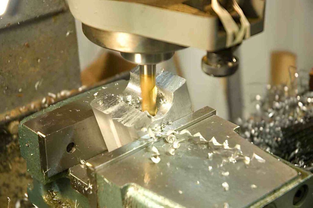
How Undercut Machining Works In Practice
Undercut machining is carried out in controlled steps. Each step helps the tool reach below a surface edge without collision and without damaging nearby geometry.
Step 1: Tool Entry At Clearance Angle
The tool enters the cutting zone at a small side angle, usually around 5° to 15°. This angle keeps the cutter away from the upper wall while the cutting edge reaches below the surface.
At this stage, only a small portion of the tool engages the material. Entry is kept light to avoid a sudden load on the cutter.
Step 2: Side Cutting Along Hidden Profile
After entry, the tool moves along the undercut path using the side cutting edge. Lollipop cutters and keyseat cutters are commonly used here.
The tool removes material under the overhang while the shank stays clear of the upper geometry. Feed is usually reduced by 20%–40% compared to open milling to keep cutting smooth in a restricted space.
Step 3: Depth Adjustment In Controlled Passes
The required depth is not reached in one cut. Instead, multiple passes are used with small step changes, often between 0.2 mm and 1 mm, depending on the material.
Each pass follows the same path, while depth is increased gradually. This prevents sudden load spikes on the tool and reduces the risk of surface marks inside the undercut.
Step 4: Final Profile Cleaning Pass
A final light pass is used to clean the undercut surface and correct small tool deflection marks. This pass uses reduced feed and minimal engagement, and ensures the hidden feature matches the design profile without leaving extra material at the base and side edges.
Tool Types Used In Undercut Machining
Undercut machining uses tools that can reach below a surface edge and cut from the side. Each tool type is selected based on feature shape, depth, and access space inside the part.
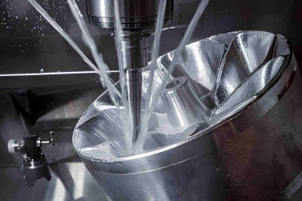
Lollipop Cutters For Curved Relief Areas
Lollipop cutters are used in parts like turbine housings, valve bodies, and mold cavities where internal reliefs sit behind a wall. The ball-shaped head reaches under the edge and machines curved undercut surfaces.
They are common in die-casting molds and aerospace components where smooth internal transitions are needed in hidden areas.
Keyseat Cutters For Straight Locking Grooves
Keyseat cutters are used in shaft keys, motor hubs, and coupling slots. These features need straight undercuts with controlled width and depth.
The side cutting edges form the groove in a single path, making them suitable for mechanical locking features in power transmission parts.
T-Slot Cutters For Fixture Plates And Base Slots
T-slot cutters are used in machine tables, fixture plates, and assembly bases where a narrow entry opens into a wider internal slot.
They are commonly used in workholding systems where bolts or clamps sit inside hidden slots below the surface.
Form Cutters For Repeated Production Features
Form cutters are used in connector housings, sealing ring grooves, and electrical enclosure slots where the same undercut shape repeats across many parts.
In these parts, the cutter profile matches the groove shape directly, so each cycle produces the same feature in stamped or machined batches.
Design Constraints And Smart Fixes For Undercut Machining
Undercut features are limited by tool access, reach, and clearance space. These constraints come from how the cutter must enter from the side and work under a surface edge. Good design avoids forcing long reach tools into tight or deep hidden areas.
Minimum Clearance For Tool Entry
Undercut features need enough side opening for tool entry at a small angle. In most CNC setups, a clearance gap of at least 1.5× tool diameter helps you to avoid collision during entry.
When space is tighter, only small cutters can be used, which reduces cutting strength and increases machining time. Adding a simple relief space near the entry zone improves tool access without changing the function.
Limiting Depth To Tool Reach Ratio
Depth is controlled by tool neck length and rigidity. A common safe range is keeping the undercut depth within 2× to 3× the tool diameter for stable cutting.
When depth exceeds this range, tool bending increases, and feature accuracy becomes harder to maintain. Splitting deep undercuts into two levels helps reduce the load on a single cutting pass.
Avoiding Sharp Internal Transitions
Sharp internal corners inside undercuts increase cutting stress and tool wear. Adding a small radius, usually matching tool size, improves cutting flow.
This also helps chip movement inside restricted areas. A smooth transition allows the cutter to pass without a sudden load change during direction shifts.
Designing for Single-Direction Tool Movement
Undercuts perform better when tool movement follows one clear direction. Reversing or complex paths inside a hidden cavity increases collision risk.
Keeping a single entry and exit path reduces tool retraction and improves machining flow. This also helps maintain a cleaner surface condition inside the feature.
Quick Tips for CNC-Machined Parts With Undercuts
Undercut features work well only when access and tool limits are planned early. Most machining problems come from tight geometry and wrong tool reach selection.
Keep Entry Side Open For Tool Movement
Undercuts need a clear entry path so the cutter can tilt and enter the feature. A blocked side forces rework or special setups.
Designers should keep enough open space near the entry face so the tool can approach without collision risk during side movement.
Match Undercut Width With Tool Neck Strength
Undercut width must match a tool that can physically reach the depth. Small width forces very thin tools, which bend easily during cutting.
In practice, narrow undercuts often show uneven surface finish when tool rigidity drops during side engagement.
Split Deep Undercuts Into Two Cutting Levels
Deep features should not be cut in a single pass. First pass removes the main material, second pass shapes the final profile.
This reduces sudden load on the tool and helps avoid deflection in steel and stainless parts where cutting resistance is higher.
Provide Exit Clearance For Tool Retraction
The cutter must leave the undercut without scraping nearby walls. Without exit space, tool marks appear at the edge during withdrawal. Clear exit direction also reduces tool stress when reversing out of the cut zone.
Select Tool Type Before Locking Geometry
Undercut shape must match available tools such as lollipop cutters or keyseat cutters. Each tool has fixed reach and cutting direction limits.
If tool selection is delayed, design changes often become necessary after machining review.
Applications Of Undercut Machining
Undercut machining is used when a feature must sit below a surface and cannot be reached with a straight tool path. These applications focus on function inside assemblies, not visible geometry.
Locking Features In Shafts And Couplings
Undercuts are used in shafts, hubs, and coupling parts where a key fits inside a hidden groove. The groove holds the key in position during rotation and torque transfer.
These features help parts stay aligned under load inside mechanical drive systems.
Sealing Grooves In Enclosures And Fluid Systems
Undercut grooves are used in pump housings, valve bodies, and sealed covers. The groove holds sealing rings that block fluid and air leakage. The position below the surface protects the seal during assembly and operation.
Retaining Slots In Fixtures And Workholding Systems
Undercuts are used in fixture plates, machine tables, and clamping bases. The slot allows bolts and clamps to sit below the surface line.
This keeps the top surface clear while maintaining firm part holding during machining.
Internal Relief Areas In Machined Components
Undercuts are used inside housings, brackets, and structural blocks to remove excess material. These relief zones prevent interference between mating parts.
They help control clearance inside assemblies without changing the outer shape of the component.
CNC Machining Methods For Creating Undercuts
Undercuts are produced using different machining methods based on access direction, material hardness, and geometry limits. Each method handles a specific type of cutting condition.
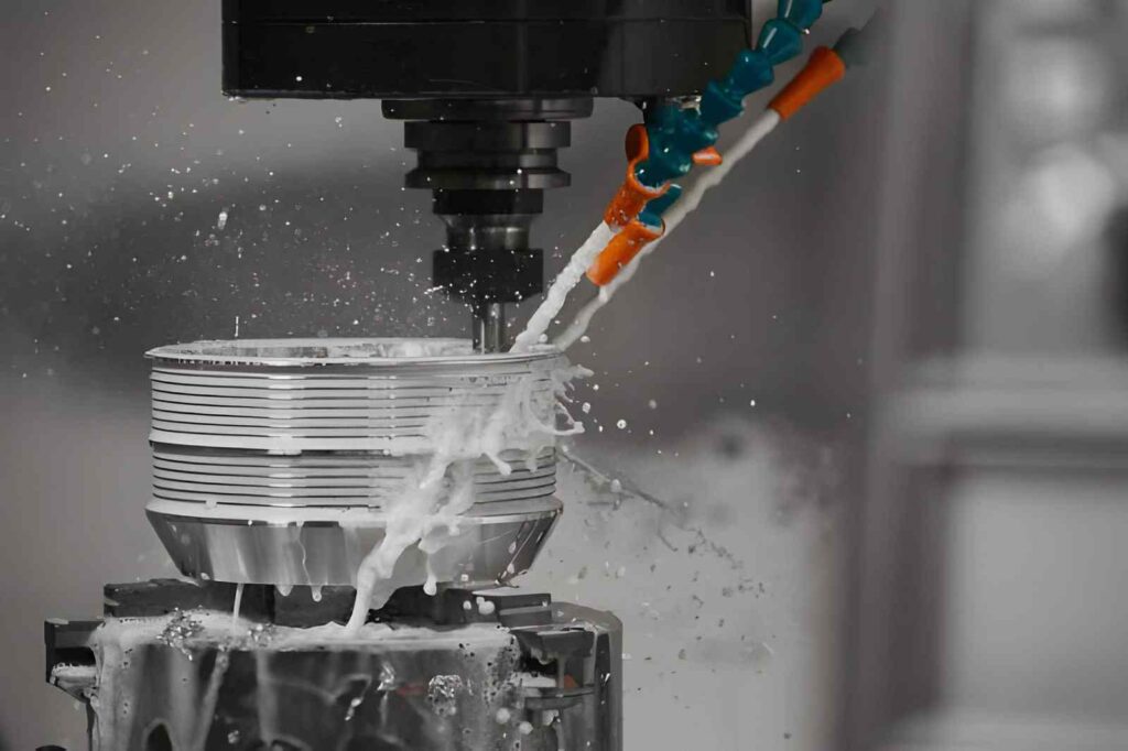
Undercut CNC Milling
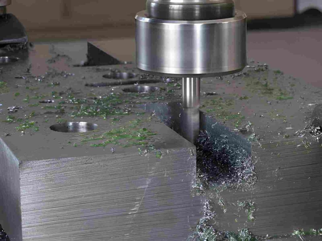
CNC milling is used for most undercut features in standard machined parts. The tool enters from a side direction and removes material below a surface edge using special cutters.
In practice, it is applied in shaft key slots, fixture grooves, and housing relief areas. The result depends on the tool reach and how much space is available around the feature.
Lollipop Cutter Method
This method uses a ball-shaped head on a narrow neck. It is used for curved undercuts inside molds and internal cavities where smooth access is needed below an overhang.
Keyseat Cutter Method
This method uses a straight side-cutting tool for grooves in shafts and hubs. It is used where a flat-bottom locking slot is required for mechanical fit.
Multi-Axis Machining
Multi-axis machining is used when the undercut sits behind angled or curved surfaces. The machine rotates the tool or part to reach hidden geometry.
It is used in aerospace brackets, mold cores, and complex housings. This method reduces the need for multiple setups and improves access to difficult internal zones.
T-Slot Milling
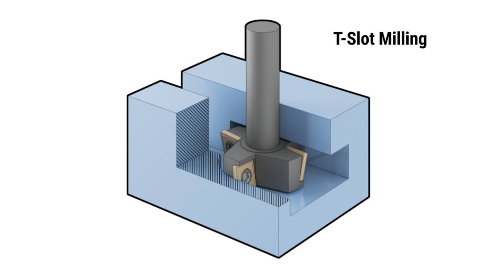
T-slot milling creates undercuts with a narrow entry and a wider base. The cutter first passes through a straight channel, then expands the cut below the surface.
It is used in fixture plates, machine tables, and clamping systems. The geometry allows hidden fastening while keeping the top surface open for machining operations.
Wire EDM
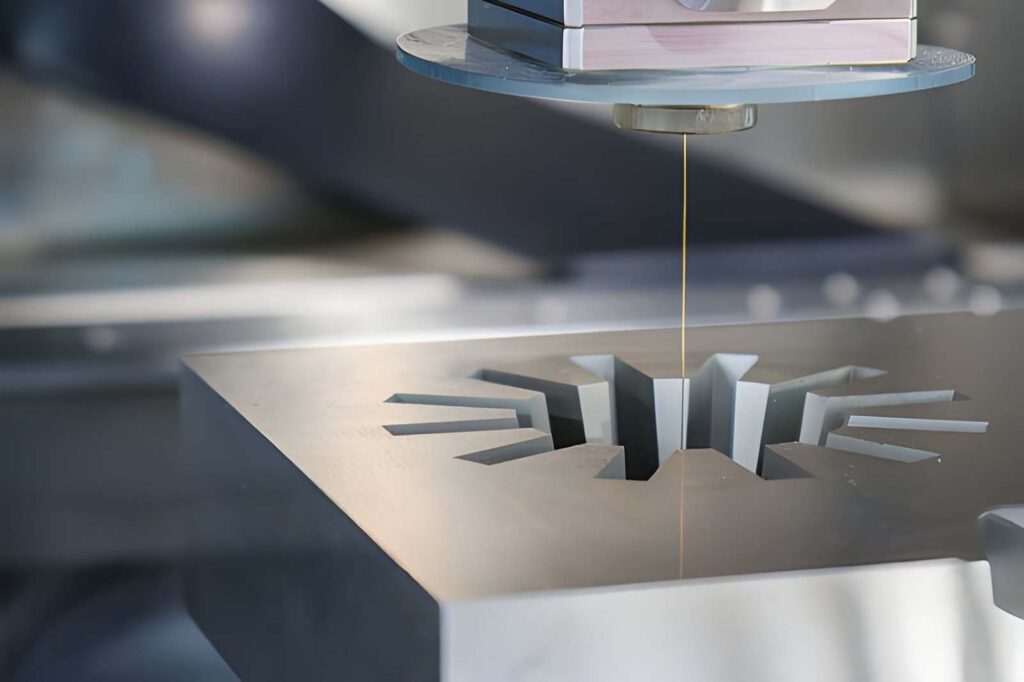
Wire EDM cuts material using a thin electrically charged wire. There is no physical tool contact, so it can reach very tight or fully enclosed internal features.
It is used in die inserts, hardened steel tooling, and deep internal cavities. It is selected when conventional tools cannot enter the cutting zone.
Surface Grinding
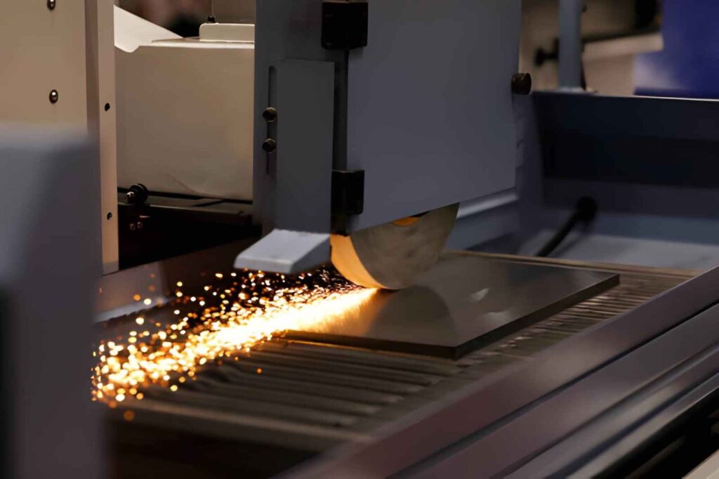
Surface grinding is used after machining to finish undercut faces. A rotating grinding wheel removes small layers of material from accessible surfaces.
It is used in tooling parts and precision assemblies where the undercut face must sit properly during final assembly.
Types of Undercuts And Their Profiles
Undercuts are classified based on tool access and final geometry requirement. From an engineering view, the key factors are load transfer, assembly fit, and how the tool can physically reach the hidden area.
Straight Undercuts With Flat Groove Profile
Straight undercuts form a rectangular groove below the surface. The bottom stays flat, and the side walls stay vertical after machining.
Engineers use this type in key slots and locking grooves in shafts, hubs, and couplings. The geometry supports direct load transfer through a fitted key, so width control and wall alignment matter more than surface finish.
Curved Undercuts With Radius Profile
Curved undercuts create a rounded base using ball or lollipop-type cutters. The transition between base and wall is smooth rather than sharp.
This profile is used in mold cavities, die components, and internal relief zones where stress concentration must be reduced. The radius helps avoid sharp corners that can weaken high-load areas in tooling and structural parts.
T-Shaped Undercuts With Expanded Base
T-shaped undercuts have a narrow entry and a wider internal section. The tool passes through a slot first, then expands the cut below the surface.
These are used in fixture systems, machine tables, and clamping bases. The geometry allows bolts and clamps to lock from below while keeping the top surface clear for machining or assembly.
Semi-Circular Undercuts With Half-Round Profile
Semi-circular undercuts follow a half-round shape along the base. The cutter defines a consistent curved seat inside the material.
Engineers use this in shaft key seats, rotating assemblies, and transmission components. The shape improves contact between mating parts and helps distribute load more evenly during rotation or torque transfer.
Dovetail Undercuts With Angled Locking Profile
Dovetail undercuts use angled side walls that create a mechanical lock. Once assembled, the feature resists pull-out in a fixed direction.
These are used in machine slides, guide rails, and tooling fixtures where parts must stay locked under load during operation.
Tapered Undercuts With Gradual Width Change
Tapered undercuts change width along depth. The geometry guides controlled entry and removal between mating parts.
These are used in alignment features and assembly guides, where controlled fit direction helps with positioning during assembly.
Spherical Undercuts With Full Curved Pocket
Spherical undercuts form a full 3D curved pocket. The surface allows multi-directional contact inside compact spaces.
These are used in sensor housings, complex molds, and internal seating areas where contact must remain uniform across curved surfaces.
Comparison Table: Undercut Types And Engineering Use
| Undercut Type | Geometry Profile | Engineering Function | Typical Application |
| Straight | Flat base, vertical walls | Direct load transfer through a fitted key | Shafts, hubs, couplings |
| Curved | Rounded base | Stress reduction inside confined geometry | Molds, dies, internal relief zones |
| T-shaped | Narrow entry, wide base | Hidden locking and clamping support below the surface | Fixture plates, machine tables |
| Semi-circular | Half-round seat | Smooth load distribution in rotating contact | Shaft key seats, rotating parts |
| Dovetail | Angled locking walls | Mechanical interlock against pull-out force | Machine slides, guide rails, fixtures |
| Tapered | Gradual width change | Controlled insertion and alignment during assembly | Positioning features, assembly guides |
| Spherical | Full curved pocket | Multi-directional seating and contact area control | Sensor housings, complex mold cavities |
Inspection & Quality Control In Undercut Machining
Undercut features are difficult to inspect because they sit below the surface and have limited tool access during measurement. Quality control focuses on geometry, tool reach effects, and hidden surface conditions.
Dimensional Inspection Of Hidden Features
Undercut dimensions are checked using CMM probing, bore gauges, or custom fixtures, depending on access. The main focus is groove width, depth, and wall position.
Because the feature is not open, inspection often requires angled probing paths. Small deviations in tool deflection can appear as width variation along the hidden profile.
Surface Condition Inside Undercut Zones
Surface condition inside undercuts is checked using visual scopes or surface replica methods. These areas are not accessible with standard contact measurement tools.
Tool marks, chatter lines, and uneven cutting paths are common issues. Inspection focuses on whether the surface allows proper assembly fit rather than visual appearance alone.
Tool Path And Geometry Verification
Tool paths are reviewed against the final geometry to confirm the correct entry angle and clearance. This helps prevent tool collision and incomplete cutting in hidden zones. Verification includes checking tool reach limits, step transitions, and side engagement zones.
Get Undercut Machining Services at YD Rapid
At YD Rapid, we machine undercut features in shafts, housings, fixture plates, and tooling parts where straight tool access is blocked. Before production, we review your CAD file and check tool entry space, undercut depth, and wall clearance so the feature can actually be machined without issues.
We also evaluate whether the geometry fits standard CNC tools such as lollipop cutters, keyseat cutters, and T-slot cutters. If access is limited, we suggest small design or tool path adjustments before machining starts.
Upload your CAD file and get an instant quote starting from $1. Our engineering team will confirm machining feasibility and tool access before production begins.

FAQs
What is an undercut in machining?
An undercut is a feature that sits below a surface and cannot be reached with a straight cutting tool. It is used for grooves, locking features, and internal relief areas.
Why are undercuts difficult to machine?
Undercuts are difficult because the tool must reach behind a surface. Limited space affects tool movement and makes cutting control more sensitive.
What tools are used for undercut machining?
Common tools include lollipop cutters for curved profiles, keyseat cutters for straight grooves, and T-slot cutters for wider internal slots.
Where are undercuts commonly used?
Undercuts are used in shafts for key slots, in housings for sealing grooves, and in fixtures for hidden clamping features.
Can all CNC machines perform undercut machining?
Not all machines can handle every undercut. The capability depends on tool access, axis movement, and available tooling setup.