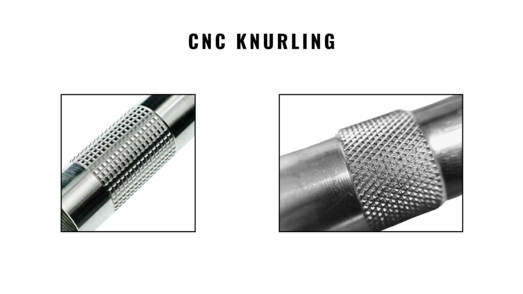
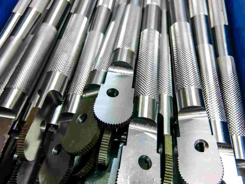
CNC knurling adds a patterned texture to round metal parts for better grip during handling and adjustment. You can see these patterns on control knobs, tool handles, thumb screws, medical fittings, and industrial equipment parts. Rather than keeping the surface smooth, manufacturers form textured lines that help users hold and rotate parts more securely.
The process is performed on CNC lathes after basic turning operations. A hardened knurling tool presses against the rotating part and gradually forms the pattern across the surface. As a result, the material shifts outward instead of getting cut away. Therefore, machinists usually machine the diameter slightly smaller before starting the knurling operation.
For example, different materials respond differently during knurling. Aluminum forms patterns more easily, whereas stainless steel requires higher forming pressure and better tool alignment. Feed rate, wheel pitch, and surface preparation also affect the final appearance. In comparison with painted grip surfaces, knurling stays directly formed into the metal surface. Thus, it remains useful for parts that face repeated manual use in industrial applications.
What Is Knurling in CNC Machining?
CNC knurling is a surface machining process. It forms patterned textures usually on cylindrical metal parts using rotating knurling wheels. The tool presses against the moving surface and gradually develops a continuous pattern across the part.
Knurling is normally performed after turning operations on CNC lathes. There are different knurled patterns, and each knurling style is selected according to part function, contact area, and product design. Manufacturers use knurling in machine components, adjustment parts, and industrial handling applications.
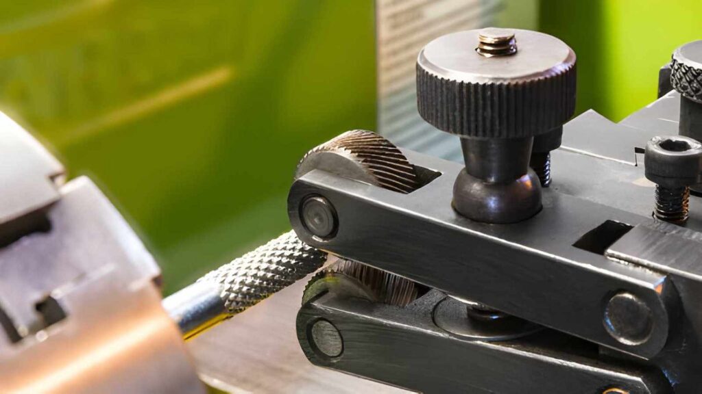
How CNC Knurling Works on Lathe Machines
The CNC knurling process follows a controlled sequence on a CNC lathe. Each step involves shaping the surface for functional use.
Workpiece Setup on CNC Lathe
First, the part is fixed in the chuck, and the rotation is set. The operator ensures the surface area is clean and ready for tool contact. This step prepares stable movement during machining.
Tool Positioning
Next, the knurling tool is aligned with the target zone. It is brought close to the surface without pressure. This allows correct positioning before contact begins.
Pattern Formation
After that, the tool presses into the rotating surface. The metal shifts and forms the knurled texture. As rotation continues, the pattern spreads across the contact area.
Axial Movement Along Part
Then, the tool moves along the length of the part. This extends the pattern evenly across the required section. Feed movement is kept steady to maintain uniform spacing.
Final Surface Check
Finally, the tool is withdrawn once the area is covered. The surface is checked during rotation for consistency. The part then moves forward for assembly or the next operation.
CNC Knurled Tool Types
CNC knurling tools differ in geometry and pattern formation. Each tool produces a specific surface texture based on contact angle, wheel shape, and cutting pressure. These tools are selected according to the part function and handling needs.
Straight Knurl Tool
Straight knurl tools use wheels with parallel tooth geometry. The contact lines run along the axis of the part. As a result, a linear texture forms on the surface. These tools are used for sliding adjustment parts, shaft guides, and components where movement control along length matters.
Diamond Knurl Tool

Diamond knurl tools use crossed wheel geometry set at opposing angles. This creates an intersecting pattern across the surface. The texture improves hand contact during rotation. Therefore, it is used on knobs, tool handles, fasteners, and tightening parts.
Diagonal Knurl Tool
Diagonal knurl tools use single-angle wheel teeth. The pattern runs in one direction across the surface. This forms a slanted grip texture. These tools are used for parts that require a controlled grip during rotation, such as adjustment rings and machine dials.
Internal Knurl Tool
Internal knurl tools are designed with smaller wheel assemblies for bore contact. They form textured surfaces inside holes. This pattern helps in press-fit locking and torque transfer inside housings, bushings, and internal sleeves.
Concave Knurl Tool
Concave tools have curved wheel profiles that match rounded surfaces. They form smooth, curved texture contact rather than sharp patterns. These tools are used in lightweight components, instrument housings, and ergonomic grip areas where softer contact is required.
Knurling techniques: Manual Knurling vs Machine Knurling
Knurling is produced either by handheld tool pressure or controlled lathe/CNC tooling. The difference shows up in how the surface load is applied and how evenly the ridge pattern forms across the diameter.
Manual Knurling
Manual knurling uses a hand-held knurl tool pressed against a rotating part. Pressure and alignment are controlled by the operator during contact. It is used for short runs, repair work, and simple shafts where minor variation in pattern depth is acceptable.
Machine Knurling (Lathe/CNC)
Machine knurling uses a fixed tool mounted on a lathe or a CNC machine. Tool force and feed are set before cutting. Typically, the forming force ranges from 200 to 1000 N. However, it depends on the material type, such as aluminum or steel. It is used when uniform pattern depth and spacing are required across production parts.
Comparison Table: Manual vs CNC Knurling
| Factor | Manual Knurling | Machine Knurling (Lathe/CNC) |
| Tool Force Control | Operator-applied pressure | Set force range (≈200–1000 N) |
| Feed Control | Hand guided during rotation | Controlled feed (e.g., 0.05–0.2 mm/rev) |
| Pattern Depth | Varies along surface length | Maintains consistent depth across the full length |
| Alignment | Manual positioning on the diameter | Fixed alignment on spindle axis (Z-axis) |
| Surface Result | Slight variation in ridge height | Even ridge spacing and height |
| Typical Diameter Range | Small one-off shafts | 5 mm to 80 mm production parts |
| Use Case | Repair work, single parts | Batch production and repeated components |
| Setup Requirement | Minimal setup time | Tool setup and machine alignment required |
Types of Knurling Patterns (By Function)
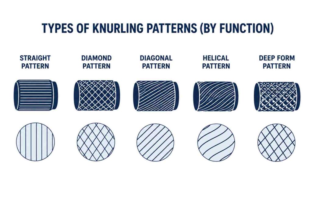
Knurling patterns control surface interaction during hand operation and part movement. Each pattern defines a different contact behavior based on groove direction and geometry.
Straight Pattern
Straight knurling forms parallel grooves along the axis of the part. The surface guides motion in a single direction without cross-resistance. It is applied to alignment shafts and positioning rods that slide during assembly stages.
Diamond Pattern
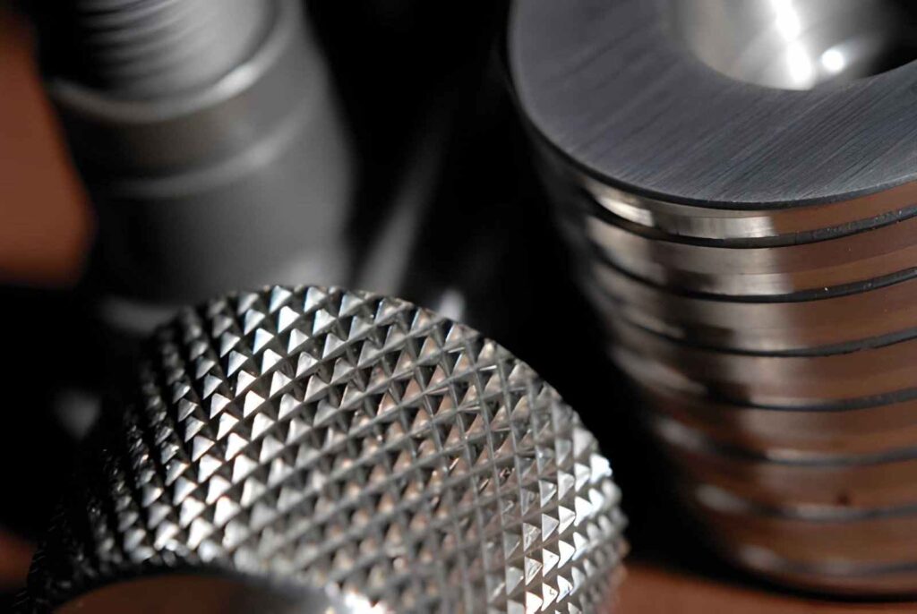
Diamond knurling creates intersecting grooves that form raised contact points. The surface supports firm hand engagement during rotational force application. It is selected for manual tightening interfaces and control elements exposed to repeated turning action.
Diagonal Pattern
Diagonal knurling produces grooves at a single angle across the surface. The contact remains balanced during rotation without aggressive locking. It is used on adjustment components that require controlled turning across repeated operation cycles.
Helical Pattern
Helical knurling forms a continuous spiral groove along the surface. The pattern supports smooth rotational movement along the part length. It is used in rotary control elements that operate through gradual angular change.
Deep Form Pattern
Deep form knurling generates increased groove depth on the surface. The contact area between the hand and the part increases during operation. It is applied in components exposed to higher manual force during mechanical adjustment tasks.
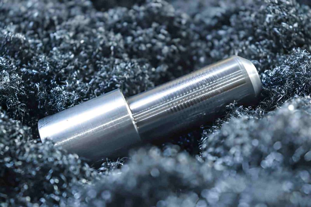
Does Knurling Change Part Diameter?
Knurling changes the surface structure by displacing material rather than cutting it away. During the process, the knurling wheels press into the rotating surface and push metal outward. This movement increases the outer surface height instead of removing stock.
As a result, the final diameter becomes larger than the pre-machined size. The increase depends on groove depth, material type, and applied forming force. Softer metals show more surface displacement, while harder metals resist deeper formation and show a smaller change.
Therefore, the part diameter must be prepared before knurling, not after it. Machinists usually reduce the turning diameter slightly so the final dimension matches the required size after pattern formation. This adjustment keeps the part within assembly limits and prevents a mismatch during fitting.
Are Serration and Knurling the Same?
No, knurling and serration are not the same.
Knurling forms a repeating raised pattern on a surface, usually diamond or straight. It is created by pressing or rolling a patterned tool against a rotating part. The goal is to improve grip on round surfaces like knobs, shafts, and handles.
Serration is different. It involves cutting a series of grooves or teeth into a surface, usually in a straight or angled direction. It is made using a cutting tool, not a rolling process. Serrations are commonly used on flat or mating surfaces where parts need to lock or prevent slipping in a specific direction.
How to Select the Right Knurl Pattern
Here are the useful tips and considerations for deciding the right knurl pattern.
Start From Part Motion Requirement
Straight knurl supports axial sliding contact along the part length. Diamond knurl supports rotation under hand load. Diagonal knurl supports controlled rotation with less surface bite. Helical knurl follows a continuous turning movement along the axis.
Check Contact Pressure at the Grip Area
Higher hand force during operation needs a diamond pattern because the intersecting grooves increase surface engagement. Lower hand effort supports diagonal or straight patterns because surface contact stays lighter.
Match Pattern With Functional Zone
Grip zones on knobs and handles use a diamond pattern for firm turning control. Adjustment collars use a diagonal pattern for smooth incremental rotation. Sliding shafts use a straight pattern to avoid resistance during axial movement.
Consider the Direction of Movement in Assembly
Linear assembly movement along a guide aligns with straight grooves. Rotational adjustment in the assembled condition aligns with diagonal or helical grooves. Fixed tightening points align with the diamond pattern.
Confirm Surface Role Before Machining
Surface used only for handling follows grip-oriented patterns. Surface used for movement follows directional patterns. This separation avoids a mismatch between tool selection and part function.
What are the Design Considerations for Knurled Parts
Knurled features need stable geometry and proper surface planning. In CNC and knurl rolling, the pattern forms based on contact pressure, so small design choices affect surface quality and final fit.
Match Diameter With Standard Knurl Tools
Knurl tools work within fixed pitch and roller sizes. When the part diameter does not match the tool range, the pattern can shift and lose clean alignment. Standard diameters help the knurl form evenly across the surface.
Keep a Continuous Cylindrical Surface
Knurling needs full tool contact along the surface. Steps, grooves, and interrupted profiles break the contact line and disturb the pattern. A smooth cylindrical section allows the tool to form a uniform ridges.
Maintain Distance From Edges and Thin Sections
During knurling, material moves outward from the contact zone. If the knurl area sits near an edge or thin wall, the surface can deform. A buffer zone helps the material stay stable during forming.
Choose Pattern Based on Function
Straight knurls support axial movement and alignment surfaces. Diamond knurls create higher surface grip for hand torque and handling. Pattern choice depends on how force transfers through the part during use.
Control Knurl Length for Clean Formation
Long knurled zones increase tool load across the surface. Shorter sections allow the pattern to form with steady contact and reduce surface distortion, especially on small-diameter parts.
Common Knurling Defects (& How to Avoid Them)
Knurling defects usually come from surface geometry, tool contact, and material movement during forming. Since the pattern forms by displacement, even small changes in setup or design can affect the final surface.
Shallow or Weak Knurl Pattern
This happens when the tool pressure does not fully engage the surface. The pattern looks faded and does not form proper ridges. Increasing contact depth and ensuring proper tool alignment along the surface helps the knurl form clearly.
Double Tracking or Misaligned Pattern
Double tracking appears when the tool does not follow a single stable path on the surface. It creates overlapping lines that weaken grip quality. Proper tool setup and correct starting position on the workpiece surface prevent this issue.
Surface Crushing on Soft Materials
Soft metals can deform under excessive knurl pressure. Instead of forming a clean pattern, the surface collapses and loses structure. Controlled feed and reduced forming load help maintain surface shape during knurling.
Edge Break or Deformation Near Ends
Knurling near edges pushes material outward, which can break the surface boundary. Leaving a safe distance from the edges helps maintain the shape and prevents edge distortion during forming.
Uneven Pattern Across Length
This occurs when tool contact varies along the knurled section. It leads to inconsistent ridge height. Keeping a straight, uninterrupted surface allows the tool to maintain steady contact across the full length.
Knurling vs Other Surface Texturing Methods
Surface texture is determined based on how the part is actually handled in assembly and use. Some parts need a direct hand grip. While some sit inside fixtures, others only need surface conditioning after machining.
Knurling
Knurling is used on rotating or hand-held parts where fingers apply torque directly. The tool presses into the rotating surface and forms a raised pattern. It is commonly applied to knobs, adjustment shafts, and control parts where slipping needs to be reduced during manual operation.
Bead Blasting
Bead blasting is used after machining to remove tool marks and change the surface feel. It does not form a pattern. The surface becomes evenly matte, which is used on covers, housings, and parts that are handled but not rotated.
Laser Texturing
Laser texturing is used when small grip zones or surface marking areas are needed without changing part shape. It is often applied to precision parts where contact points must stay controlled, such as medical or instrument components.
EDM Texturing
EDM texturing is used mainly on tooling surfaces like molds. It forms controlled surface pits that help material release during molding cycles. It is not used on typical production parts but on manufacturing tools.
Milling Serration
Milling serration is used on flat or clamping faces where movement must stay restricted. The cutter creates straight grooves that help parts stay fixed inside jigs or fixtures during machining or assembly.
Table: Knurling vs Other Methods
| Method | Where It Is Seen in Parts | What Happens on Surface | Why It Is Used |
| Knurling | Hand-held shafts, knobs | Raised diamond or straight ridges formed by pressure | Improves grip during manual turning |
| Bead Blasting | Finished metal covers | Uniform matte surface without pattern | Removes machining marks and evens surface feel |
| Laser Texturing | Precision contact zones | Small controlled marks or patterns | Defines grip or marking without changing geometry |
| EDM Texturing | Mold cavities and dies | Controlled pit-like surface | Helps material release in molding |
| Milling Serration | Fixture and clamp faces | Straight cut grooves on the surface | Stops movement during holding or clamping |
When Knurling Is Not the Right Choice
Knurling is useful for grip, but it is not suitable for every part. This process applies force on the surface, so the design, material, and function must support that deformation.
Thin Wall or Lightweight Parts
Knurling pushes material outward during formation. Thin walls or lightweight sections can deform under this pressure. In such cases, the surface loses shape, and the part may not hold its designed geometry after machining.
Mating Surfaces
Parts that need smooth contact or an accurate fit should not use knurling. The raised pattern creates uneven contact, which affects alignment and reduces proper seating in assemblies.
Soft or Low-Strength Materials
Materials like soft aluminum grades or certain plastics cannot support strong surface displacement. Knurling can crush the surface instead of forming a clean pattern, which reduces usable grip.
Small Diameter Features
Very small diameters limit the tool contact area. The knurl pattern becomes inconsistent, and the surface may show uneven tracking instead of a clean grip structure.
Surfaces with Tight Clearance in Assembly
If a knurled area sits near another mating component, the raised ridges can interfere during assembly. In such cases, smooth or lightly finished surfaces are used instead of knurling.
Materials That Produce Good Knurled Patterns
Knurl quality depends on how the material reacts under surface pressure. The pattern forms by displacement, so material flow and hardness control how clean the ridges appear.
Mild Steel
Mild steel produces stable knurl patterns because it deforms in a controlled way under pressure. The surface holds the ridge shape without cracking, so it is commonly used for knobs, shafts, and general machine handles.
Aluminum (6061 / 6082)
Aluminum forms knurls easily because it is soft and cuts clean under forming pressure. It is often used for lightweight control parts, but surface pressure must stay controlled to avoid ridge collapse in thin sections.
Brass
Brass gives clean and sharp knurl edges. It does not harden quickly during forming, so the pattern stays consistent across the surface. It is used in fittings, decorative grips, and instrument parts.
Stainless Steel (303 / 304)
Stainless steel holds the knurl shape well, but it needs a higher forming force. Once formed, the pattern stays durable under repeated handling, which makes it suitable for industrial control parts and shafts.
Free-Machining Carbon Steel
Free-machining steel grades produce consistent knurl patterns with less tool load. The material flow stays uniform during forming, which helps maintain even ridge height across longer surfaces.
Can Knurled Parts be Painted and Anodized?
Yes, knurled parts can be anodised or painted, but surface geometry affects coating behavior. The raised ridges and valleys do not allow a fully flat coating layer, so material builds differently across the surface during finishing.
Anodising on knurled aluminium follows the surface shape and forms a thin oxide layer across both peaks and grooves. Color can look slightly uneven on sharp or deep knurls because light reflection changes on angled surfaces. Painting behaves similarly. Spray reaches the outer ridges first, while deeper areas may get lighter coverage unless surface preparation is controlled before coating.
Is is Possible to Clean Knurled Parts?
Yes, knurled parts can be cleaned and polished, but the method depends on how deep the pattern is and what the part is used for.
Cleaning is usually done using ultrasonic cleaning, solvent wash, or light brushing to remove chips, oil, and debris trapped inside the knurl grooves. For industrial parts, compressed air is also used to push out material from deeper patterns before assembly or finishing.
Polishing is possible, but it is limited to light surface smoothing. Because knurling is a raised pattern, aggressive polishing can flatten the ridges and reduce grip. In most cases, polishing is used only on the outer peaks or non-functional areas where appearance matters more than grip performance.
What are the Main Cost Drives for CNC Knurling
Knurling cost depends on material resistance, surface size, tool engagement time, and production quantity. Since the process forms the surface through pressure contact, machining time and tool load directly affect overall cost per part.
Material type
Hard materials like stainless steel increase tool pressure and reduce feed rate, which increases machining time. Softer materials like aluminum allow faster forming and lower cycle time.
Knurl length
Longer knurled sections keep the tool in contact for more time. This increases cycle time directly and raises cost per part.
Pattern type
Diamond knurls need more controlled engagement compared to straight knurls. This adds a slight extra machining time during formation.
Part size and diameter
Small diameters reduce tool stability during contact. This often requires a slower feed to maintain pattern quality, which increases cost.
Batch size
Single or low-quantity jobs carry a higher setup share per part. Larger batches reduce cost because setup time is distributed across more parts.
Can Plastic Parts be CNC knurled?
Yes, plastic parts can be knurled, but the result depends on material stiffness and requires careful attention.
Hard plastics like POM (Delrin), nylon, and ABS can hold knurled patterns because they resist surface tearing during forming. The pattern forms by displacement, so the material needs enough strength to keep the ridge shape after the tool pressure is applied.
Soft plastics, such as polyethylene or low-density materials, do not hold clean knurl patterns. Instead of forming sharp ridges, the surface compresses and loses definition, which reduces grip quality.
Get CNC Knurling Services for Functional Grip Surfaces From YD Rapid
At YD Rapid, we use CNC knurling to create controlled grip patterns on shafts, knobs, and handling parts. Each part is reviewed before machining to match the knurl type with the function and geometry.
- Knurling on the lathe and CNC turning setups for round parts
- Controlled forming for aluminum, steel, brass, and selected plastics
- Stable pattern depth across the full surface length
- Pre-machining review for diameter, access, and tool load
- Production support from prototype to batch runs
Contact us, or you can upload your CAD file to our platform and get instant feedback from our engineers. We will help you decide on tool selection, surface suitability, and pattern type, so the grip surface forms correctly and matches the intended function.

FAQ’s
What is the difference between knurling and CNC grooving?
Knurling forms a pressed surface texture, and it changes the surface shape by displacement. Whereas grooving removes material to create a cut channel and creates defined depth through cutting action.
Knurling builds grip on outer surfaces, while grooving defines functional paths such as sealing, seating, and tool clearance.
Which knurling tool works best for CNC knurling?
Usually, tool selection depends on the pattern requirement and material response. Diamond knurl tools can handle general-purpose gripping surfaces. While straight knurl tools facilitate directional movement.
- For harder materials, a stronger wheel construction with sharp tooth geometry is better under higher forming pressure.
- For softer metals, a standard wheel can perform better without surface tearing.
How is diamond knurling done on CNC or manual milling for aluminum?
Diamond knurling on aluminum uses intersecting wheel pressure to form a cross pattern. On CNC lathes, the tool engages the rotating surface and feeds along the axis to build the pattern.
On manual setups, the operator applies steady tool pressure while rotating the workpiece. Aluminum forms patterns easily, so controlled feed prevents surface distortion.
What is G32 knurling?
G32 is a CNC lathe command used for single-pass threading style movement with synchronized spindle rotation. It helps control the exact tool movement along a programmed path.