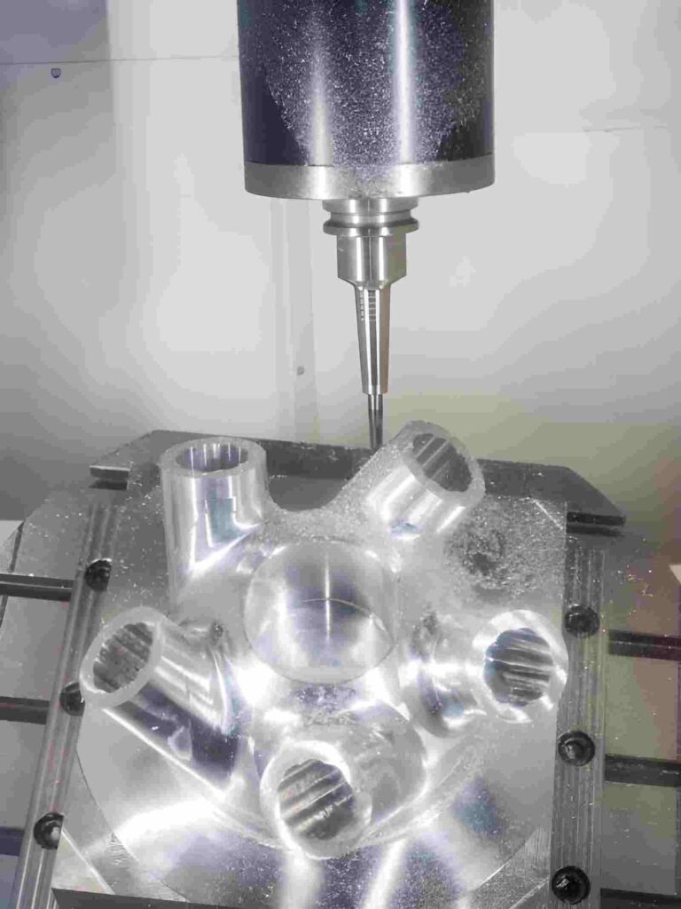
Complex CNC machining involves parts with complex geometry and multiple feature interactions. This means parts entail deep cavities, thin walls, undercuts, and multi-axis surfaces that standard CNC setups cannot handle. Such a feature influences tool access, cutting load, and how the part reacts during machining.
Such a machining process is primarily used in aerospace, medical, energy, and tooling parts. These components need controlled geometry across several directions rather than simple flat features. Therefore, you rely on multi-axis machining, staged operations, and planned(optimized) toolpaths instead of single-pass cutting.
Generally speaking, complexity comes from how features connect, not just from shape alone. A deep pocket near a thin wall changes cutting behavior. A long tool reach increases bending under load. Thus, you must plan tool selection, cutting sequence, and engagement at every stage.
This article explains:
- How complex CNC machining works,
- Impact of complex geometry on cost and lead time
- What challenges appear in deep and multi-axis features?
- How can you control the tool behavior during cutting?
What are the Design Considerations for Complex CNC-Machined Parts
Complex CNC parts must meet design intent that matches cutter size, depth limits, setup changes, and chip exit space. If these are ignored, shops change tool diameter, reduce depth per pass, and split machining into extra setups. As a result, this increases cycle time and adds extra tool paths.
Internal Feature Size Sets Cutter Diameter
Small internal corners and slots force the use of a small cutter. A 3 mm corner requires a 3 mm tool. That tool cannot take large step-downs. So material removal happens in short vertical increments, often below 1 mm per pass in deeper sections.
Depth Controls Stepdown Range
Depth above 30 to 50 mm with small cutters forces reduced stepdown. A 10 mm cutter, cutting deep pockets, uses multiple layers instead of full-depth cuts. Each layer reduces engagement to avoid tool bending. This increases the number of passes along the wall.
Internal Corners Add Extra Tooling Pass
If the corner radius is smaller than the cutter radius, shops bring a second, smaller tool. That adds a separate corner pass after roughing. Without it, the corner stays rounded to the first tool radius, often matching 50 to 100% of the cutter diameter.
Thin Walls Require Stock Left Before Finishing

Thin walls are left with extra material during roughing. Typical allowance remains around 0.2 to 0.5 mm per side. Side cutting applies a force that pushes thin sections. Final passes remove remaining stock using lower engagement to reduce wall movement.
Multi-Setup Features Shift Positioning
Features across multiple faces depend on re-clamping accuracy. Each setup adds a small positional change, often in the range of 0.01 – 0.05 mm, depending on fixture condition. Connecting features across faces increases mismatch risk unless kept in one setup.
Pocket Width Controls Engagement Level
When pocket width equals cutter diameter, engagement stays at 100 percent during cutting. This increases radial load and reduces feed rate. Increasing pocket width by 10–20 percent reduces continuous full engagement and allows partial cutting paths.
Deep Cavities Trap Chips Inside Cut Zone
Closed pockets hold chips under the tool path. Chips remain between the cutter and the surface and are recut. Shops use air blast or coolant flow, but full clearance is not guaranteed. Open relief channels reduce chip accumulation in deep areas.
Dense Features Interrupt Tool Path
Multiple holes or steps on one surface force repeated tool entry and exit. Each entry adds tool lift and reposition time. This increases the cycle count directly. Grouped feature placement reduces tool interruption per surface.
Non-Critical Surfaces Increase Machining Time
If drawings do not separate functional and non-functional areas, shops apply finishing passes on all faces. This increases tool engagement time without affecting part function. Only mating faces and locating surfaces receive controlled finishing passes.
Machining Techniques for Complex CNC Machining
Here are the commonest techniques for machining complex features in parts.
3 Axis Milling for Simple Cuts & Profiles
3-axis machining handles basic pockets, profiles, and flat surfaces. It removes bulk material first before any detailed work. Most complex parts start here because it clears open areas and sets reference faces for later setups.
3+2 Axis Positioning for Angled Features
3+2 axis uses indexed positioning instead of continuous movement. The part rotates to a fixed angle, then standard milling starts. This method is used for angled holes, slanted faces, and features that cannot be reached from one direction.
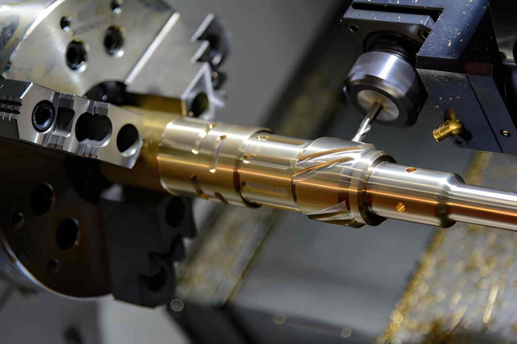
5 Axis Simultaneous Machining for Freeform Surfaces
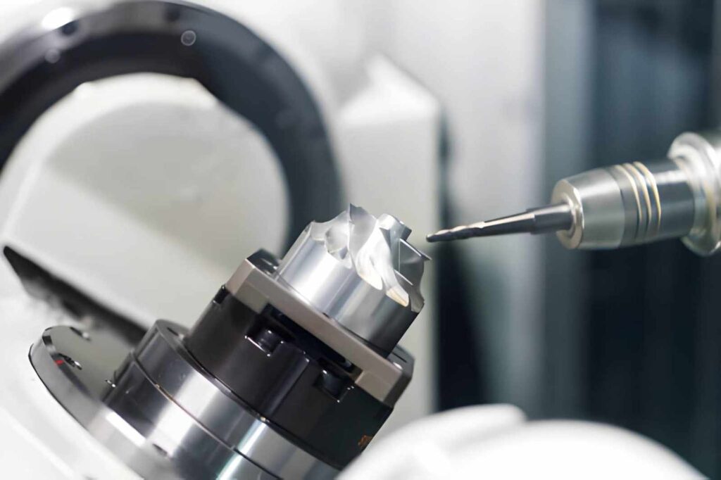
5-axis machining moves the tool and part at the same time. It reaches curved surfaces, deep contours, and complex transitions in one setup. So, this reduces repositioning and helps maintain consistent tool access across curved geometry.
Adaptive Roughing for High Material Removal
Adaptive roughing uses controlled tool engagement instead of full-width cuts. The tool follows a dynamic path that keeps cutting load steady. This method is used in deep pockets and large stock removal areas.
Rest Machining for Secondary Tool Cleanup
Rest machining removes material left after larger tools. A smaller cutter follows the previous tool paths and clears remaining corners and tight zones. This step appears after roughing to reach areas that larger tools cannot enter.
Trochoidal Milling for Deep Slots
Trochoidal milling uses circular cutting motion with controlled step movement. The tool avoids full engagement and reduces load in deep slots. This method helps maintain cutting action in narrow and deep features.
Drilling and Peck Drilling for Deep Holes
Straight drilling handles shallow holes in one pass. Peck drilling breaks deep holes into repeated entry and exit cycles. This helps remove chips and reduces tool load in deep internal channels.
Contour Finishing for Surface Definition
Contour finishing follows the final shape of walls and curved surfaces. It uses a lighter cutting depth compared to roughing. This technique defines the final surface condition on vertical walls and blended geometry.
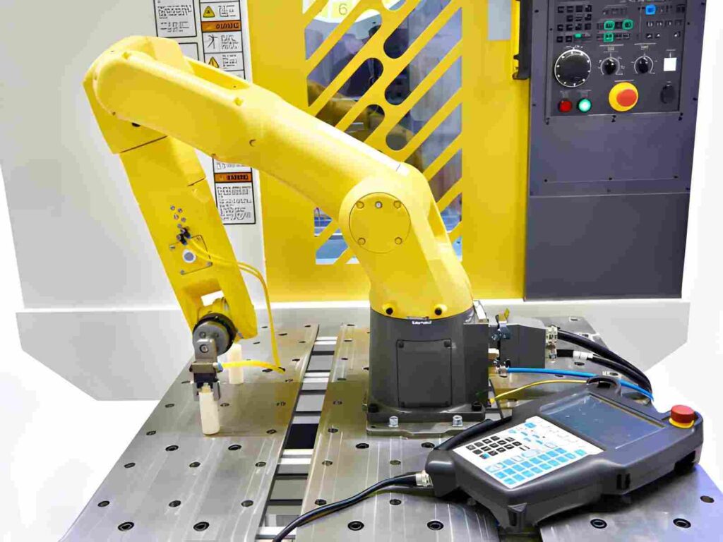
Multi-Setup Machining for Full Part Access
Complex parts require multiple setups to reach all faces. Each setup exposes new surfaces for cutting. Fixtures hold the part in place while machining continues from different orientations.
Machining Techniques for Complex CNC Machining
| Technique | Axis Type | Parts Made | Typical Use |
| 3 Axis Milling | 3 Axis | Brackets, plates, basic housings | Flat faces, open pockets, simple profiles |
| 3+2 Axis Machining | Indexed 3+2 Axis | Mount blocks, angled brackets, fixture parts | Angled holes, tilted faces, multi-directional drilling |
| 5 Axis Simultaneous Machining | 5 Axis | Aerospace parts, impellers, turbine parts | Curved surfaces, continuous 3D geometry |
| Adaptive Roughing | 3 Axis / 5 Axis | Mold blocks, die inserts, heavy stock parts | Large material removal in deep pockets |
| Rest Machining | 3 Axis / 5 Axis | Precision housings, mold cavities | Small leftover areas after roughing |
| Trochoidal Milling | 3 Axis | Deep slots, narrow channels | Narrow deep cuts with controlled engagement |
| Drilling / Peck Drilling | 3 Axis | Hydraulic manifolds, engine blocks | Deep holes and internal channels |
| Contour Finishing | 3 Axis / 5 Axis | Brackets, molds, housings | Final wall and surface finishing passes |
| Multi-Setup Machining | 3 / 4 / 5 Axis | Complex multi-face assemblies | Parts requiring re-orientation for access |
Complex CNC-Machined Parts Examples
Here are some of the common examples of parts that normally keep intricate features and geometry.
Aerospace Structural Brackets
These brackets combine mounting holes, pockets, and angled faces in one body. One side usually carries load paths, while the other side includes weight reduction pockets. Machining needs multiple setups because no single direction reaches all faces.
Medical Device Housings
These housings include sealed cavities, threaded ports, and internal channels. Internal space is limited, so small cutters are used for pocket areas. Wall thickness is controlled because uneven cutting force can affect the fit between mating parts.
Automotive Transmission Components
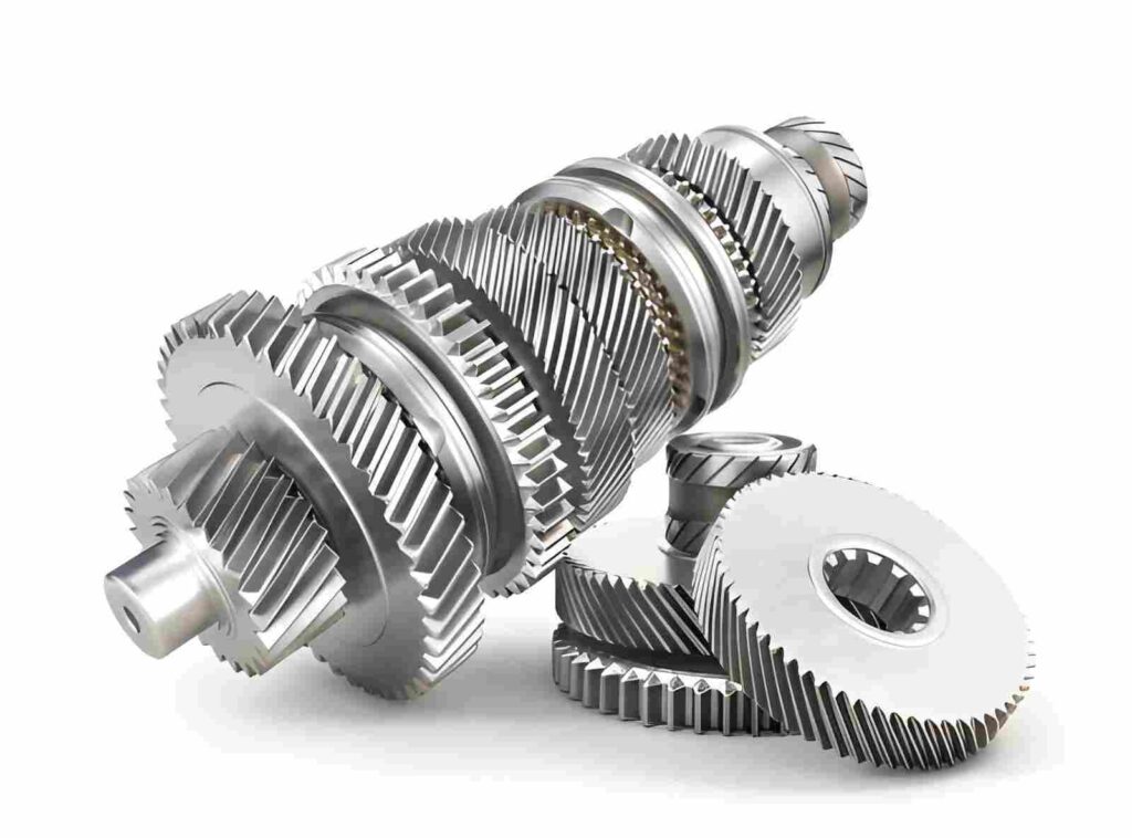
These parts include intersecting bores and internal oil channels. Several features are inside one block, so drilling and milling paths cross each other. Chip removal becomes important because many channels stay enclosed after machining.
Hydraulic Manifold Blocks
Manifolds contain multiple drilled passages inside a solid block. Each passage connects at different depths and angles. Machining starts with drilling, then moves to milling for pocket access and cross connections between channels.
Robotics Joint Housings
These housings include bearing seats, bolt patterns, and curved outer profiles. Different faces carry different functions, so machining rotates between setups. Bearing seats need controlled cutting paths to match assembly components.
Mold and Die Inserts
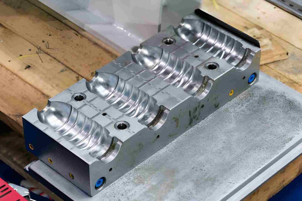
These inserts form cavities with varying depths and fine surface areas. Roughing removes bulk material first, then finishing tools follow the cavity shape. Deep areas require long tools, which changes the cutting approach at different depths.
Heat Sink Components
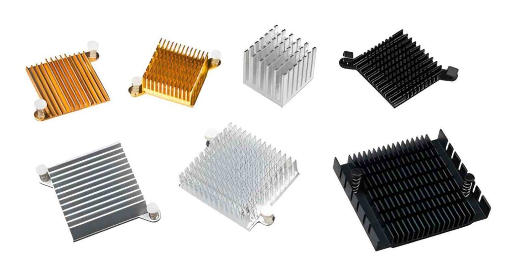
Heat sinks include many thin fins spaced closely together. Each fin is cut using narrow tools with repeated passes. Tool access between fins limits cutting speed and requires careful path planning to avoid tool contact between ribs.
Defense Equipment Mounts
These mounts combine thick support areas with angled fixing points. Load-bearing zones are machined first, followed by angled surfaces in separate setups. Feature placement often requires re-orientation of the part to reach all faces.
Surface Finishing Techniques for Complex CNC-Machined Parts
Bead Blasting for Uniform Matte Finish
Bead blasting uses glass beads under controlled air pressure to treat the full surface. It removes light tool marks and creates a uniform matte texture. It is mostly applied to aluminum and stainless steel parts, but it does not change the dimensional size in a controlled way for tight-fit surfaces.
Anodizing for Aluminum Surface Protection
Anodizing builds an oxide layer on aluminum parts through an electrochemical process. Type II anodizing is used for cosmetic color finishes, while Type III hard anodizing increases surface hardness and wear resistance. Thickness growth must be considered on mating surfaces.
Passivation for Stainless Steel Parts
Passivation removes free iron from stainless steel surfaces using nitric or citric acid treatment. It improves corrosion resistance without changing part geometry. It is commonly used after CNC machining of 304 and 316 stainless steel components.
Electropolishing for Smooth Metal Surfaces
Electropolishing removes a thin surface layer using controlled electrochemical dissolution. It reduces micro peaks left from machining and improves surface smoothness. It is used in medical, food-grade, and fluid-handling components.
Powder Coating for Durable External Protection
Powder coating applies dry polymer powder and cures it under heat. It forms a thick protective layer on steel and aluminum parts. Coating thickness usually ranges from 50 to 150 microns, which affects assembly fits if not planned.
Chemical Conversion Coating for Aluminum and Magnesium
Conversion coating creates a protective chemical layer on aluminum or magnesium surfaces. It improves corrosion resistance and provides a base for painting or sealing. It adds minimal thickness compared to coating methods.
Tumbling for Small Complex Parts
Tumbling uses abrasive media in a rotating barrel to smooth edges and remove burrs. It is used for small CNC parts with multiple edges and internal transitions. It reduces sharp edge conditions without controlled dimensional removal.
Brushing for Linear Surface Texture
Brushing uses abrasive belts or pads to create directional surface lines. It is applied to stainless steel and aluminum panels for a controlled aesthetic finish. The direction of brushing must match the visible face orientation in assembly.
Impact of Complex Design Choices on Cost and Lead Time
Design choices affect tool selection, machining time, setup count, and CAM effort. Each geometry decision shifts one or more of these, which directly reflects in cost and delivery time.
Small Internal Features Increase Tool Requirement
Small corner radii and narrow slots force small cutters. Once smaller tools enter the process, more tool changes appear during machining. That also increases preparation work before cutting starts.
Deep Geometry Extends Cutting Duration
Deep pockets and tall features need multiple Z levels. Each level removes a portion of the material. As depth increases, spindle time grows because cutting cannot stay in one continuous pass.
Multi-Face Parts Increase Setup Work
Features spread across different faces require re-clamping. Each setup needs alignment before machining continues. This adds handling time between operations and extends overall production flow.
Tight Corners Add Extra Toolpath Step
When the internal radius is smaller than the main cutter, a second tool is required. That creates an additional pass only for corner zones. This adds one more step in the machining sequence.
Thin Walls Extend Finishing Stage
Thin walls cannot be brought to the final size in rough cuts. Material is removed in light finishing passes instead. That increases the number of final passes before the part is released.
Dense Features Increase Tool Movement
High feature count on one surface increases tool entry and exit cycles. The cutter stops more often between cuts. This adds non-cutting movement within the same machining cycle.
Poor Access Increases Repositioning Work
If a feature cannot be reached in one direction, the part is rotated or re-clamped. Each reposition introduces alignment work before cutting resumes. This extends the overall machining flow.
Complex Surfaces Increase CAM Effort
Curved and freeform surfaces need detailed toolpath planning. CAM work increases because each surface requires its own cutting strategy before machining begins.
What Is Different in Complex and Standard Part Machining
Standard machining deals with open geometry where tools reach features from one direction. Complex machining includes deep pockets, thin walls, angled faces, and intersecting features that need multiple tool directions and staged cutting.
| Factor | Standard CNC Machining | Complex CNC Machining |
| Part geometry | Flat faces, simple pockets, drilled holes | Deep cavities, thin walls, angled and curved surfaces |
| Tool access | One-directional access | Multiple directions required |
| Setups | One setup in most cases | Two or more setups common |
| Tool selection | Standard end mills and drills | Mix of small cutters, long reach tools, ball nose tools |
| Cutting method | Full passes with simple toolpaths | Layered cutting with roughing and finishing stages |
| Feature interaction | Features stay independent | One feature affects nearby cutting behavior |
| Cycle time | Short machining cycle | Longer cycle due to extra steps and tool changes |
| Programming | Simple toolpaths | Multi-axis toolpath planning is needed |
| Surface work | Basic finishing pass | Separate finishing + post process like blasting or coating |
Get Complex CNC Machining Services at YD Rapid
At YD Rapid, we machine complex parts with deep cavities, thin walls, angled surfaces, and multi-setup geometry. We handle parts where straight tool access is blocked and where features need staged machining across different directions.
Before production, we review your CAD file to check tool access, feature depth, wall thickness, and setup requirements. This helps define how each feature will be reached and which machining sequence fits the geometry.
We also check whether your part fits 3-axis, 3+2-axis, or 5-axis machining. If access is limited, we suggest practical adjustments in design or machining approach so production stays workable without extra rework.
Our precision CNC machining service includes:
- Deep pocket and cavity machining
- Thin-wall component machining
- Multi-axis surface machining
- Multi-setup part machining
- Complex fixture and housing parts
Upload your CAD file and get an instant quote starting from $1. Our engineering team reviews manufacturability and tool access before machining begins.

FAQs
What is complex CNC machining used for?
It is used for parts with deep pockets, thin walls, angled faces, and multi-axis geometry. These parts appear in aerospace, medical, automotive, and tooling applications where simple machining cannot reach all features.
Which materials are common in complex CNC machining?
Aluminum, stainless steel, titanium, and engineering plastics are commonly used. Each material reacts differently during cutting, so tool selection and cutting depth change based on material type.
Why do complex parts need multiple setups?
Different faces of the part cannot be reached from one direction. Each setup exposes new surfaces for machining. This allows full feature access across all sides of the component.
What causes higher machining costs in complex parts?
Cost increases due to small tool use, extra setups, deeper cutting stages, and longer CAM programming time. Each added feature increases tool movement and machining time per part.
What is the role of 5-axis machining in complex parts?
5-axis machining allows tool and part movement at the same time. It reaches curved surfaces and angled features in one setup, which reduces repositioning and improves access to complex geometry.
How is surface quality controlled after CNC machining?
Surface quality is controlled using finishing passes during machining and post-process treatments like bead blasting, anodizing, electropolishing, or coating, depending on material and application.