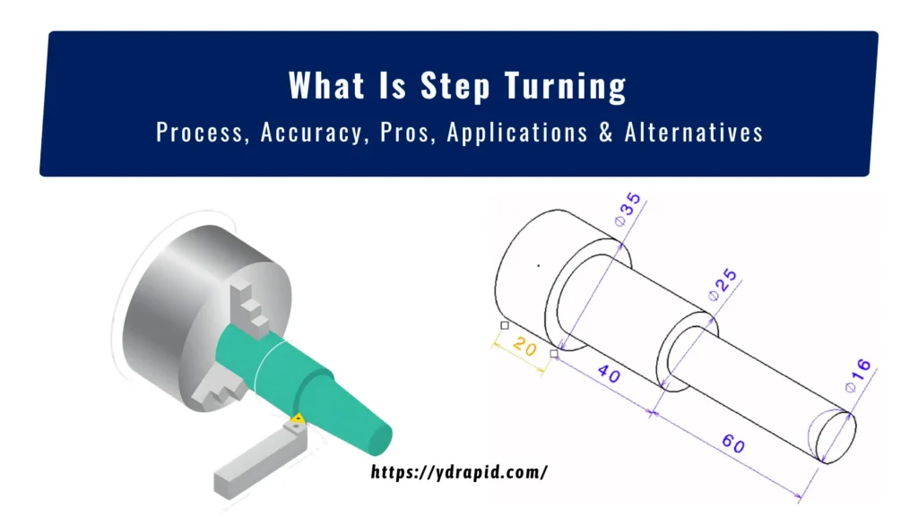
Step turning is used to machine shafts with multiple diameters, where each section has a defined fit.
In practical manufacturing, especially in CNC machining, understanding step turning helps ensure your shaft design meets assembly and tolerance requirements.
These sections are made to match bearings, bushings, gears, or threaded ends that sit at fixed positions. The shoulder between two diameters acts as a stop face during assembly and controls axial location.
What Is CNC Step Turning?
Step turning is used when a shaft needs different diameters along its length. Each section is machined to a set size, and the change between them forms a shoulder. These shoulders are used to locate parts like bearings, gears, or spacers during assembly.
The operation is done on a lathe by cutting one section at a time. The tool moves along the axis and stops at fixed positions to create each step. It is common in shaft work where multiple fits are required on a single part.
How is Step Turning Done on a Lathe?
Step turning follows the drawing, where each diameter and its position along the shaft are already defined. The process is done in stages, with attention to both size and shoulder location. In most production setups, this type of operation is performed using CNC turning to ensure consistent positioning and repeatable accuracy across multiple parts.
Work Setup and Reference Point
The part is held in a chuck or between centers based on length and rigidity. A facing cut is made first to create a clean reference face. This face is used as the starting point for all length measurements along the shaft.
Marking Step Positions
The tool is aligned with the reference, and positions for each step are set along the axis. On CNC, these come from programmed coordinates. On manual machines, the operator uses the carriage scale or dial to locate each position.
Rough Turning of Each Section
Material is removed from each section in rough passes. The tool moves along the length of that step and cuts it down to near size. Heavier cuts are used here to remove bulk stock before finishing.
Forming Shoulders Between Steps
When the tool reaches the end of a section, it stops to create a shoulder. This edge defines where the next diameter begins. If needed, a small relief is added to avoid interference during assembly.
Finishing to Final Size
Light cuts are applied to bring each diameter into the final size. Feed and depth are reduced to improve surface condition and dimensional control. Each step is finished separately to avoid size overlap.
Checking Size and Position
Each diameter is measured using micrometers, and lengths are checked from the reference face. If a section is out of size, a correction is made before moving to the next step. This keeps errors from carrying forward.
Tools and Equipment Needed for Step Turning Operation
Step turning needs a basic lathe setup, but the quality depends on tool selection, work holding, and measurement control. Each setup element affects how accurately the diameters and shoulders are produced on the shaft. In production, the focus stays on stability, repeat positioning, and clean cutting at each step.
Lathe Machine Setup
A CNC lathe or conventional lathe is used depending on production volume. The machine must hold a stable spindle speed and rigid axis movement, since step turning requires repeated positioning along the Z-axis. Any vibration or backlash directly affects shoulder location and diameter consistency.
Cutting Tools
Single-point turning tools are used for step turning. Carbide inserts are preferred for steel and alloy materials due to higher wear resistance. Tool nose radius is selected based on finish requirement, usually between 0.2 mm and 0.8 mm for clean shoulder edges.
Workholding Devices
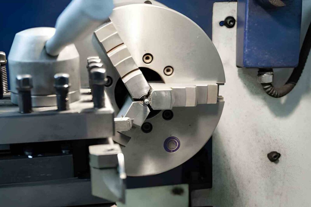
The workpiece is fixed using a 3-jaw chuck for short shafts or between centers for long components. Tailstock support is used when the length increases to avoid deflection during cutting.
Measuring Tools
Measurement tools are used during and after machining to control each step dimension. Vernier calipers are used for quick checks, while micrometers are used for final diameter control. Dial indicators help verify runout before machining begins and ensure correct alignment.
Coolant and Chip Control System
Coolant is used to reduce heat during cutting, especially when machining multiple steps on steel or alloy materials. It also improves tool life and surface finish at shoulder transitions. Chip evacuation is important to avoid re-cutting
What Is the Difference Between Step Turning vs Taper Turning
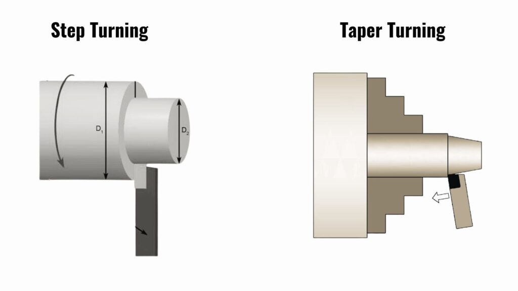
Step turning keeps the tool feed parallel to the spindle axis. Therefore, each diameter is cut at a fixed position along the shaft. It helps create clear shoulders that act as physical stops during assembly.
On the other hand, taper turning changes the tool path angle relative to the axis. So the diameter reduces gradually from one end to the other. This produces a conical surface used for seating and alignment rather than fixed positioning.
Table 01: Comparing Step Turning Vs Taper Turning
| Parameters | Step Turning | Taper Turning |
| Tool path angle | 0° to the spindle axis (parallel feed) | Typically 1° to 15° relative to the axis, depending on the taper |
| Diameter change | Discrete steps (e.g., Ø50 → Ø40 → Ø30 mm) | Continuous reduction (e.g., Ø50 → Ø30 mm over length) |
| Length control | Each step length is defined individually (e.g., 40 mm, 60 mm) | Total taper length is defined between two diameters |
| Positioning reference | Measured from the faced datum along the axis | Defined by start diameter, end diameter, and taper angle |
| Geometry transition | Sharp 90° shoulder between diameters | Smooth angled surface, no shoulder |
| Assembly function | Shoulders act as axial stops for bearings, gears | Parts seat along taper using surface contact |
| Machine setup | Straight longitudinal feed using the carriage | A compound slide set to an angle or taper attachment is used |
| Typical taper ratios | Not applicable | Common ratios like 1:10, 1:20, Morse taper standards |
| Measurement method | Micrometer for diameter and caliper for length | Micrometer for diameters and a sine bar or gauge for angles |
| Error sensitivity | Position error affects the shoulder location | Angle error affects the full-length fit and contact |
Step Turning Common Applications Across Industries
Step turning is used where one shaft carries multiple working zones. Each zone supports a different part, like a bearing, gear, or coupling. The shoulders between diameters control position during assembly.
Automotive Shafts and Transmission Parts
Step turning is common in shafts where power transfer parts sit at fixed locations. Gearbox shafts use stepped diameters for gears and bearings. Camshafts use steps for journals and lobes. Steering shafts also use steps to match couplings and support bearings.
Machine Tool and Industrial Shafts
Industrial machines use step turned shafts for power and motion transfer. Motor shafts need separate diameters for bearings, pulleys, and couplings. Pump shafts use steps to locate impellers and seal zones. Conveyor rollers also use stepped sections for drive and support areas.
Fixtures and Tooling Parts
Step turning is used in jigs and fixtures where positioning matters. Locator pins use stepped sections to control depth inside holes. Clamping shafts use steps to guide movement and locking points. Assembly fixtures also use stepped rods for repeat alignment.
Heavy Equipment Components
Large machines use step turning in load-carrying parts. Hydraulic rods use different diameters for sealing and mounting ends. Crane shafts use steps to handle load zones and bearing locations. Agricultural equipment shafts use steps for attachments and drive sections.
Is CNC Turning the Same as CNC Milling?
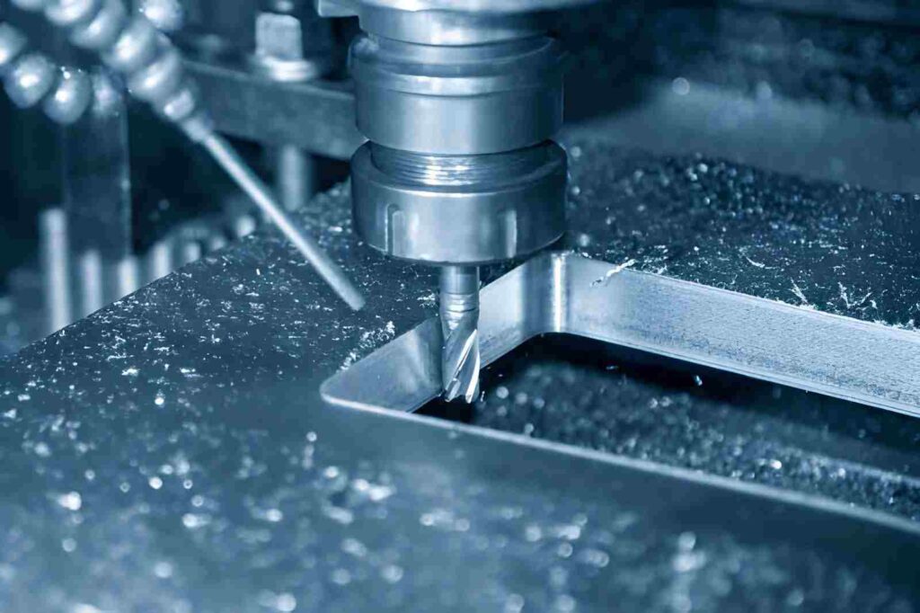
Turning and milling are both cutting techniques in CNC machining. But they work in opposite ways. The main difference lies in their cutting mechanism. In turning, the workpiece rotates, and the tool remains fixed. While in milling, the cutting tool rotates, and the piece remains fixed. Usually, it is done in multiple axes (X, Y, Z, AB).
Turning is used for round parts like shafts and rods. The tool stays mostly fixed while the material spins against it. Thus, it can optimally produce cylindrical shapes, steps, grooves, and threads.
Milling is used for flat surfaces, slots, pockets, and complex shapes. The tool rotates at high speed, and the workpiece stays fixed or moves under the tool. This allows more freedom in shape compared to turning.
So overall, turning is focused on rotational parts, while milling is used when shapes are not centered around a single axis.
9 Common Types of CNC Turning Operations
Turning operations on CNC lathes differ based on tool path, axis control, and material removal direction. Each operation produces a specific geometry and is selected based on function, not just shape.
Type #1. Facing Operation
Facing is used to create a flat reference surface at the end of a workpiece. The tool moves radially from the outer diameter toward the center, perpendicular to the spindle axis (90° cutting approach). It sets the datum for all axial measurements in CNC setups.
Type #2. Straight Turning
Straight turning reduces the diameter along the axis using a tool feed parallel to the spindle axis (0° feed direction). It is used for cylindrical sections like shafts, typically with a depth of cut ranging from 0.5 mm to 3 mm per pass, depending on the material.
Type #3. Step Turning
Step turning creates multiple diameters on a single axis using linear axial indexing. Each diameter is cut in separate Z-axis positions, forming shoulders at 90° transitions between sections. Common step differences range from Ø2 mm to Ø30 mm, depending on assembly fit.
Type #4. Taper Turning
Taper turning uses angled tool movement relative to the spindle axis, typically between 1° and 15° included angle. It can be defined using compound slide angle, CNC interpolation, or taper attachment. It is used when the diameter changes gradually over length instead of step transitions.
Type #5. Grooving
Grooving cuts narrow recesses using radial tool movement into the rotating part. Groove widths typically range from 1 mm to 10 mm. It is used for retaining rings, O-ring seats, and clearance slots with controlled depth.
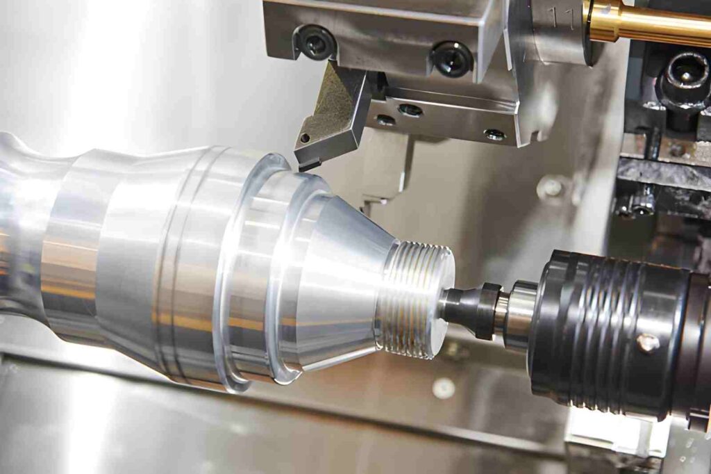
Type #6. Thread Turning
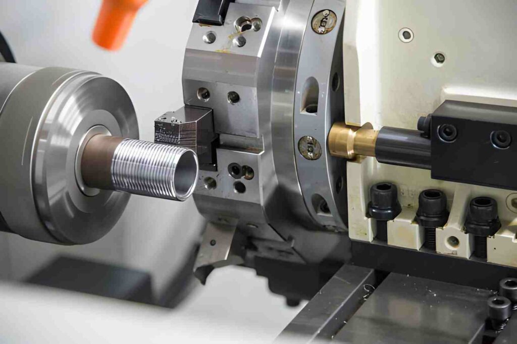
Thread turning generates helical profiles using synchronized spindle rotation and linear feed. Common thread angles include 60° (ISO metric), 55° (Whitworth), and 29° (ACME). Pitch accuracy depends on CNC lead synchronization.
Type #7. Parting (Cut-Off)
Parting separates finished components using a radial plunge cut into the workpiece centerline. Typical blade widths range from 1 mm to 3 mm. It is used at the final machining stage after all turning operations are complete.
Type #8. Knurling
Knurling is a cold-forming operation where patterned rollers press into the surface. Common patterns include straight, diagonal, and diamond (30°–45° crossing angle). It does not remove material but displaces it to form grip texture.
Type #9. Boring Operation
Boring enlarges and corrects internal holes using an internal cutting tool. The tool moves parallel to the spindle axis (0° feed). Typical tolerance control can reach ±0.02 mm, depending on machine rigidity and tool overhang length. Used after drilling to improve hole accuracy and surface finish.
Common Challenges in Step Turning and How They Are Handled
Step turning issues usually show up in assembly, not during machining. A small shift in shoulder position or diameter affects how bearings, gears, and spacers sit on the shaft. Most problems come from setup control, tool alignment, and how each step is finished in sequence.
The solutions are based on how engineers handle these issues on CNC and manual lathes during production.
Shoulder Position Shift Between Steps
In step turning, every shoulder decides where a component stops on the shaft. If the Z position drifts even slightly, the bearing or gear will not sit at the correct location. This becomes critical in assemblies with stacked components.
Solution: Fixed datum and step-by-step position control
- Start all measurements from a single-faced reference surface
- Lock Z zero before machining each step section
- Use CNC coordinate checks before every diameter change
- Verify shoulder position after rough cut, not only at the final pass
Diameter Inconsistency Across Steps
When multiple diameters are machined in sequence, tool wear and offset changes can create a mismatch between sections. This becomes apparent when mating parts slide onto different steps and feel either loose or tight.
Solution: Consistent tool condition and in-process checking
- Measure each diameter immediately after cutting
- Adjust the tool offset after the first rough pass if wear is seen
- Keep the same cutting tool for all step transitions when possible
- Use the finish pass on all steps under the same feed and speed
Tool Deflection on Long Shafts
Long shafts behave differently during cutting because material support is uneven. When the tool loads increase on deeper cuts, slight deflection can change the diameter consistency along the step length.
Solution: Support setup and controlled cutting depth
- Use the tailstock support for long workpieces
- Reduce the depth of cut during roughing on extended sections
- Keep the tool overhang short to reduce the bending force
- Finish cuts with a lower feed to stabilize the final size
Shoulder Edge Quality at Step Transitions
Shoulders are functional faces where parts rest. If the tool pulls away too fast or lingers at the edge, it can leave marks that affect seating between components.
Solution: Controlled approach and finishing strategy
- Approach the shoulder with a steady feed, not an abrupt stop
- Use a light finishing pass on the shoulder face
- Add a small chamfer if assembly allows edge relief
- Retract the tool cleanly without rubbing at the transition point
Difference Between Step Turning and Chamfering
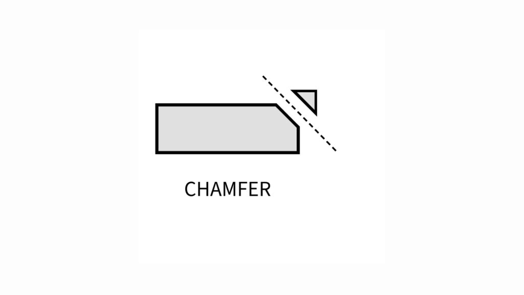
Step turning is used to machine a shaft into different diameter sections along its length. Each section is cut separately on the lathe, and the change in diameter creates a shoulder that defines the position for parts like bearings, gears, or spacers.
In comparison, chamfering is an edge finishing operation where a sharp corner is removed by cutting a small, angled face. It is usually applied at the end of machining or between features to reduce stress concentration, improve assembly fit, and prevent edge damage during handling.
Table 02: Comparing step turning vs chamfering
| Parameters | Step Turning | Chamfering |
| Purpose | Creates multiple diameter sections on a shaft | Removes sharp edges at corners or ends |
| Geometry produced | Stepped profile with shoulders | Angled edge (bevel) at transition or end |
| Tool movement | Linear feed along the spindle axis (Z-axis) with diameter changes | Short angled cut at edge (typically 30°–45°) |
| Cutting area | Full cylindrical surface in each step | Only the edge or corner area |
| Dimensional control | Controls diameter and step length | Controls edge size, not shaft geometry |
| Functional role | Used for locating bearings, gears, and spacers | Used to ease assembly and remove sharp corners |
| Typical application | Shafts, pins, multi-diameter components | Bolt ends, shaft edges, hole entrances |
How Accurate is Step Turning in Practice?
Step turning gives good control over shaft diameters, but it is not ultra-precision work. On a CNC lathe, each step diameter usually stays within about ±0.02 to ±0.05 mm when the setup is stable and tools are in good condition. Step lengths are generally controlled within ±0.05 mm from the reference face.
On a manual lathe, accuracy depends more on operator control and measuring between cuts. Diameter variation can sit around ±0.05 to ±0.10 mm, especially when multiple steps are made one after another. Small shifts often come from tool wear and repeated repositioning along the shaft.
Difference Between Step Turning and Facing
Step turning and facing are both lathe operations, but they are used for different machining approaches. For instance, step turning is used to create multiple diameters along the length of a shaft.
In contrast, facing is used to make the end surface of a part flat.
Table 03: Step turning vs facing
| Parameters | Step Turning | CNC Facing |
| Main purpose | Forms different diameter sections on a shaft | Creates a flat surface at the end of a part |
| Tool movement | Moves along the length of the shaft (Z-axis) | Moves across the face toward the center (radial movement) |
| Shape produced | Stepped cylindrical profile with shoulders | Flat circular surface |
| Cutting area | Along the shaft length | At the end, face only |
| Function in parts | Used for locating bearings, gears, and spacers | Used to create a reference surface or finish end |
| Machining stage | Main shaping operation | First or final setup operation |
| Measurement focus | Diameter and step length | Flatness and face alignment |
Contact YD Rapid for Step Turning and CNC Machining Support
At YD Rapid, we provide our customers with complete support from design to finish. Once you submit your design or CAD file, our engineers will review your part drawings before machining to confirm whether step turning, CNC turning, or other lathe operations fit your design.
Our designers check shaft geometry, step positions, and fit requirements so each diameter is planned with a clear machining sequence.
We also support full CNC machining workflows for shafts, pins, and multi-diameter components where step turning is part of a larger production process. This helps reduce rework between roughing, turning, and finishing stages. You can benefit from us by getting:
- Free DFM review before machining starts
- Guidance on step turning vs CNC turning selection
- Support for shafts, pins, and multi-diameter parts
- Process planning for turning, milling, and finishing stages
- Practical feedback on tolerances and setup strategy
Contact us today or send us your drawing to our team for a practical machining review before production begins.

FAQ’s
What tools are best for step turning?
Carbide single-point tools are commonly used for steel and alloy shafts. High-speed steel tools are suitable for low-volume or softer materials, but tool wear is higher.
How can I decide step sizes in a shaft?
Step sizes are based on mating parts like bearings, gears, or bushings. Each diameter matches a specific fit requirement defined in the assembly drawing.
Can step turning be done in one setup?
Yes, most step-turning jobs are completed in a single setup. This helps maintain alignment between steps and reduces errors caused by re-clamping.