Machining titanium is the process of shaping titanium metal using cutting tools and CNC machines to produce precise components. It involves operations such as CNC turning, milling, drilling, and boring to remove material and achieve the required geometry and tolerance.
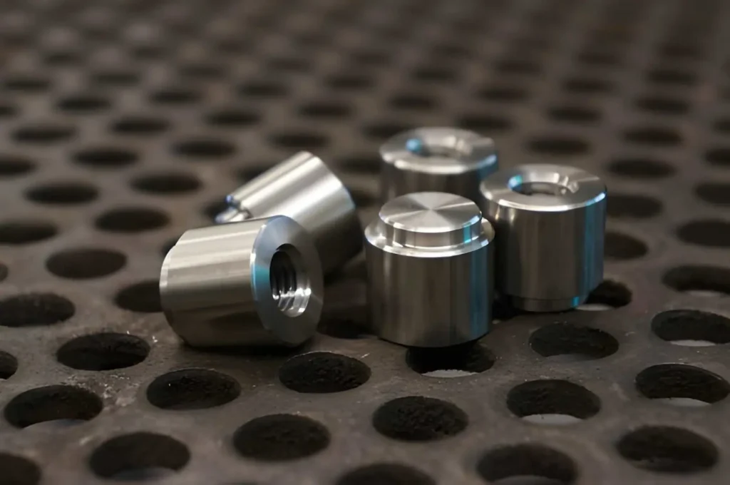
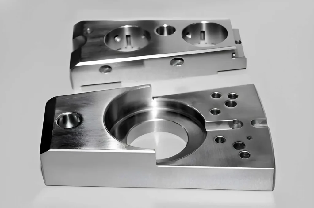
Titanium machined parts are used when components need to remain strong without adding excessive weight. You’ll find it in brackets, housings, and load-bearing parts where aluminum cannot handle the load and steel adds too much mass.
From a machining perspective, the main challenge is not cutting the shape but keeping the process stable throughout the operation. Thin and slender sections and longer features add another layer of difficulty. The part can deflect slightly under cutting load, which affects accuracy and can introduce chatter if the setup is not rigid.
In this article, you will learn:
- How titanium behaves during machining
- Ehy tool wear and heat become major issues
- How cutting strategy, tool selection
- Setup decisions help improve stability and part quality
What Is Titanium CNC Machining?
Titanium CNC machining is the controlled cutting of titanium where speed, heat, and tool load are managed to keep the process stable.
Here are the considerations for machining titanium.
- Cutting speed (typically, 20 to 60 m/min) is used to manage heat at the tool edge.
- Feed rate is kept constant to prevent rubbing (typically 0.05 to 0.2 mm/tooth) based on tool size.
- The depth of cut is set to maintain a constant load, usually 0.5 to 2 mm in finishing and light roughing.
- The heat must be controlled by coolant or air blast to avoid damage to the tools.
- Applied in components where a strength/weight ratio is required, like aerospace brackets, medical implants, and load-bearing housings.
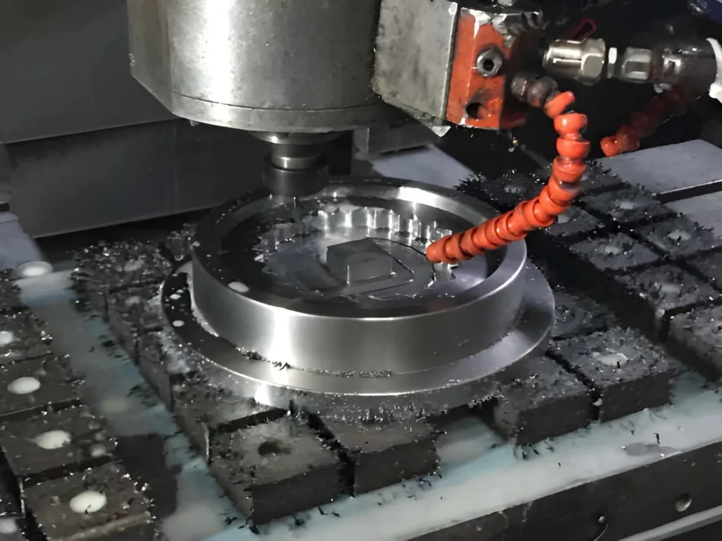
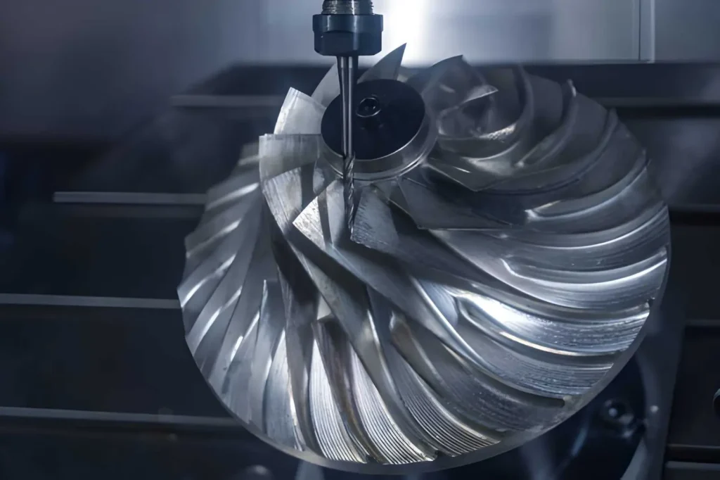
Side Milling of Titanium (Tool Engagement and Material Removal)
In titanium CNC machining, vertical walls and edges are machined with side milling, where the tool load needs to remain in control. Titanium is relatively sensitive to cutting heat and cutting force, and therefore, cutting does not rely on aggressive removal but on consistent engagement.
Cutting with the Tool Side Instead of the Tool End
Side milling uses the flute side of the end mill to cut along the wall. This avoids continuous loading at the tool tip, which tends to overheat in titanium.
- Cutting happens on the side flutes, not the tool center
- The tool tip is kept out of full contact to reduce heat buildup
- Cutting speed stays low, typically 20 to 50 m/min
- Sharp tools are required to prevent material adhesion on the edge
Radial Engagement Along Vertical Surfaces
Radial engagement controls how much of the cutter diameter is in contact with the titanium. This directly affects heat generation and tool stability.
- Engagement is usually limited to 10 to 25% of the tool diameter
- Higher engagement increases cutting force and tool wear risk
- Lower engagement keeps the temperature more stable
- Feed rate is adjusted to maintain chip formation without rubbing
How Geometry Is Formed Through Side Passes
Titanium walls are not finished in a single cut. Geometry is formed through controlled passes to keep the load consistent on the tool.
- Roughing removes material in steps and leaves 0.2 to 0.5 mm stock
- Finishing pass removes the remaining material in a single controlled cut
- Step-over is kept constant to avoid load variation on the cutter
- Final pass is run at reduced load to control deflection and surface finish
Parameters and Cutting Strategy in Titanium Machining
Titanium side milling is controlled mainly by heat and tool stability, not material removal rate. The cutting strategy is set to avoid sudden force spikes, since titanium reacts quickly to overload and temperature buildup.
Radial Engagement Control
Radial engagement is kept low in titanium machining to prevent heat concentration at the cutting edge. Once engagement increases, tool wear rises quickly, and cutting becomes unstable.
- Usually kept around 10 to 25% of the tool diameter
- Lower engagement keeps cutting temperature under control
- Higher engagement increases tool wear and edge chipping risk
- Finishing cuts use minimum engagement for stability
Titanium Machining Axial Depth of Cut and Stepdown Control
Axial depth in titanium machining is limited because the material pushes back against the tool instead of breaking cleanly. As a result, this increases deflection if the cut is too deep.
- Roughing typically stays around 0.5 to 2 mm per pass
- Finishing is reduced to 0.2 to 0.5 mm for stability
- Consistent stepdown avoids load shock on tool engagement
- Thin sections require a lower depth to prevent vibration
Titanium Machining Feed Rate and Chip Load Control
Feed rate in titanium machining is adjusted to avoid rubbing and overheating. An incorrect chip load can likely damage tools in titanium.
- Chip load is usually maintained at 0.05 to 0.2 mm/tooth
- Too low feed causes heat buildup and tool rubbing
- Too high feed increases edge stress and chipping
- Feed must match engagement to keep cutting stable
Titanium Machining (Climb Milling vs Conventional Milling)
Cut direction has a direct impact on tool load behavior in titanium machining. Force stability is more important than chip removal speed.
- Climb milling is preferred for stable cutting and lower force
- It reduces friction at entry and improves tool life
- Conventional milling increases rubbing and heat generation
- Used only when setup or geometry restricts climb cutting
Toolpath Strategy (Single Pass vs Multi-Pass Finishing)
Titanium machining rarely uses aggressive single-pass finishing because it leads to deflection and inconsistent surface quality.
- Roughing leaves 0.2 to 0.5 mm stock allowance
- Multi-pass finishing improves control on thin or flexible walls
- Single-pass finishing is only used on rigid, well-supported setups
- Final pass uses light engagement to reduce heat and distortion
What Affects Accuracy and Surface Quality in Titanium Machining
During machining, titanium reacts strongly to force and heat. Thus, any variation in tool load or cutting condition directly affects wall accuracy and surface quality.
Tool Deflection and Wall Accuracy
Tool deflection occurs when cutting forces push the tool away from the intended path. In titanium machining, this is more visible because the material applies continuous resistance during cutting.
- Long tool overhang increases bending and wall size error
- Cutting force variation shifts the tool away from the programmed path
- Thin-wall features show higher dimensional deviation after finishing
Preventive measures:
- Reduce tool overhang to improve rigidity
- Use lower radial engagement during finishing passes
- Leave 0.2 to 0.5 mm stock for the final correction pass
Chatter and Vibration Effects
Titanium has low damping capacity, so vibration builds quickly during machining operations. This directly affects both surface finish and dimensional control.
- High radial load triggers chatter on unsupported features
- Flexible setups increase vibration marks on machined surfaces
- Unstable cutting produces uneven surface texture and tool marks
Preventive measures:
- Reduce radial engagement to stabilize cutting forces
- Improve fixture rigidity and part support
Burr Formation and Edge Quality
Titanium does not shear cleanly under unstable cutting conditions, which leads to burr formation at edges. This is common in finishing and exit cuts.
- Material deformation at exit edges creates burrs
- Higher feed variation increases tearing at the edge
- Worn tools increase burr size and reduce edge sharpness
Preventive measures:
- Use sharp cutting tools to maintain a clean edge formation
- Apply a consistent feed rate to avoid tearing at edges
- Add light finishing passes to reduce burr size before deburring operations
Design Guidelines for Titanium Machining (DFM)
Part design in titanium machining has a direct impact on cutting load, heat generation, and tool stability. Bad geometry results in deflections and vibration during cutting, causing problems in accuracy and accelerated tool wear. Proper design makes the engagement of tools constant and predictable.
Titanium Machining Wall Support and Stability
Wall design controls how much the part resists cutting force during machining. In titanium, unsupported or thin walls easily deflect under load.
- Wall thickness below 2 mm increases deflection risk in titanium
- Wall height above 4 to 6× tool diameter increases vibration during cutting
- Internal ribs or nearby support features improve stiffness during machining
- Shorter and thicker walls give better dimensional control after finishing
Finishing Allowance for Wall Accuracy
Finishing allowance helps control final accuracy because titanium does not respond well to heavy single-pass cutting.
- Typical stock allowance for walls is 0.2 to 0.5 mm per side
- Roughing removes bulk material, and finishing stabilizes the final size
- No allowance leads to a high tool load and a poor surface finish
- Final pass with light engagement improves straightness and wall quality
Geometry Design for Load Reduction
Geometry has a direct effect on cutting force distribution in titanium machining. Sharp and deep features increase stress on the tool.
- Internal corner radius should be at least 0.5 to 1 mm to reduce stress
- Deep, narrow slots increase tool engagement and should be avoided when possible
- Sudden thickness changes create load spikes during cutting
- Open and gradual transitions improve chip flow and cutting stability
Titanium vs Aluminum vs Steel: How to Choose the Right Material for Your Parts
Material selection for CNC machining depends on the strength, weight, and service conditions of the part. You also need to consider machinability factors like cutting speed, tool wear, and heat generation during processing.
Let’s take a look at how titanium, aluminum, and steel behave during machining and their characteristics.
| Parameter | Aluminum (6061/7075) | Stainless Steel (304/316) | Titanium (Ti-6Al-4V) |
| Density (g/cm³) | 2.7 | 7.9 – 8.0 | 4.4 – 4.5 |
| Ultimate Strength (MPa) | 290 – 570 | 520 – 750 | 900 – 1100 |
| Hardness (HB) | 95 – 150 | 150 – 220 | 330 – 360 |
| Thermal Conductivity (W/m·K) | 150 – 170 | 14 – 16 | 6 – 8 |
| Machinability (% vs steel=100) | 250 – 300% | 45 – 60% | 20 – 30% |
| Typical Cutting Speed (m/min) | 200 – 600 | 60 – 120 | 20 – 60 |
| Tool Wear Rate | Low | Medium–High | Very High |
| Heat Concentration | Low | Medium | Very High |
| Chip Formation | Smooth, long chips | Stringy, work-hardening | Segmented, hot chips |
| Coolant Requirement | Moderate | High | Critical (targeted) |
| Risk Issues | Burrs, built-up edge | Work hardening, tool wear | Tool failure, thermal damage |
| Surface Finish (Ra µm) | 0.8 – 3.2 easy | 1.6 – 3.2 controlled | 1.6 – 6.3 difficult |
| Cycle Time (relative) | 1× (fastest) | 1.5 – 2× | 3 – 4× |
| Tooling Cost Impact | Low | Medium | Very High |
| Part Cost Index | 1× | 2 – 3× | 4 – 5× |
| Dimensional Stability | Good | Very good | Sensitive to heat |
| Thin Wall Capability | Good but flexible | Strong but heavier | Possible but expensive |
Selection Notes!
When Aluminum is the Right Choice
Choose aluminum if:
- You need fast machining cycles
- You want low tool wear and cost
- Part needs heat dissipation (electronics housings)
- Weight reduction is important
- Geometry has deep pockets or complex milling
Avoid aluminum if:
- High wear or friction is expected
- Threads will face repeated load
- Extreme strength is required
When Stainless Steel Makes Sense
Choose stainless steel if:
- Parts need to perform in wet or chemical environments
- You need a higher strength than aluminum
- Wear resistance matters (shafts, fittings)
- Surface must remain stable over time
Avoid stainless if:
- You need fast machining or low cost
- Complex geometry increases cycle time heavily
When to Choose Titanium
Choose titanium if:
- Strength-to-weight ratio is critical
- Part operates in high heat (>300°C)
- Corrosion is extreme (marine, chemical)
- Biocompatibility is required (medical implants)
- Failure is not acceptable (aerospace parts)
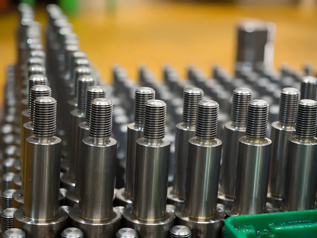
Typical titanium parts:
- Aerospace brackets and fasteners
- Medical implants and surgical components
- High-performance engine components
- Marine corrosion-resistant fittings
Avoid titanium if:
- Aluminum or steel meets the requirements
- Budget or lead time is limited
- Design includes deep cavities or thin features
Typical Applications of Machined Titanium Parts
In titanium machining, side milling is mainly used where vertical walls, slots, and edge faces must stay accurate under cutting load.
Aerospace Titanium Structural Components
In aerospace applications, titanium is used where strength and weight must stay balanced in structural layouts. Side milling is applied when walls and mounting faces need controlled accuracy during machining.
- Brackets with a wall thickness typically around 2 to 5 mm, where deflection control is required
- Structural ribs where perpendicularity affects assembly fit
- Mounting faces held within ±0.02 to 0.05 mm tolerance range
- Thin-wall frames, where machining stability directly affects the final geometry
Automotive Titanium Performance Parts
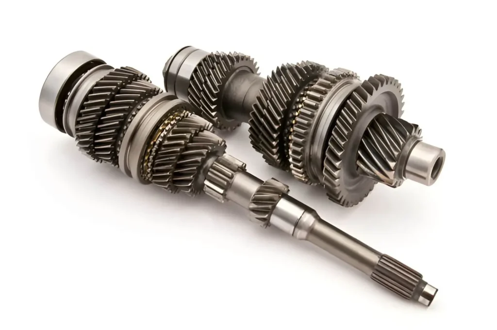
In automotive systems, titanium side milling is used in areas exposed to heat, vibration, and repeated loading. The machining focus stays on maintaining alignment and stiffness.
- Engine brackets exposed to thermal cycling above 100°C
- Turbo and exhaust support housings with stable wall sections
- Lightweight arms where stiffness must remain consistent under load
- Spacer and alignment features where fit accuracy is critical in assembly
Electronics Titanium Enclosures and Frames
Electronics applications use titanium where compact size and stable alignment are required. Side milling is used to maintain accurate housing geometry and clean edge formation.
- Thin-wall device housings in the range of 1 to 3 mm thickness
- Mounting frames for sensor or PCB alignment
- Connector faces requiring accurate vertical wall positioning
- Internal support structures in compact assemblies
Medical Titanium Precision Components
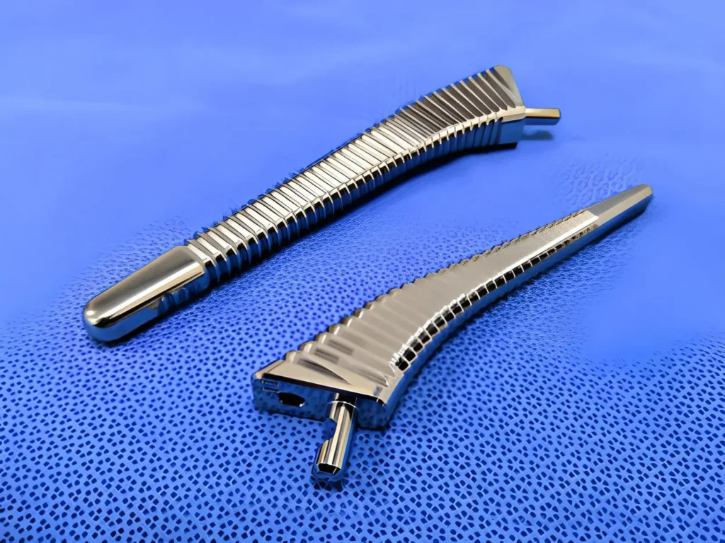
Medical applications place strict demands on dimensional control and surface stability, especially for components that interact directly with the human body. Titanium is commonly used in these cases due to its strength and biocompatibility.
- Surgical instrument handles with defined side profiles
- Implant housings requiring stable geometry during use
- Guide frames are maintained within ±0.02 mm accuracy
- Small connectors where edge quality affects assembly fit
Energy Titanium System Components
In energy systems, titanium is used in environments involving pressure and corrosion. Side milling supports accurate sealing and structural interfaces.
- Valve bodies with machined side sealing surfaces
- Flow control housings exposed to pressure conditions
- Mounting interfaces in offshore or chemical systems
- Structural connectors requiring corrosion resistance
Robotics Titanium Structural Parts
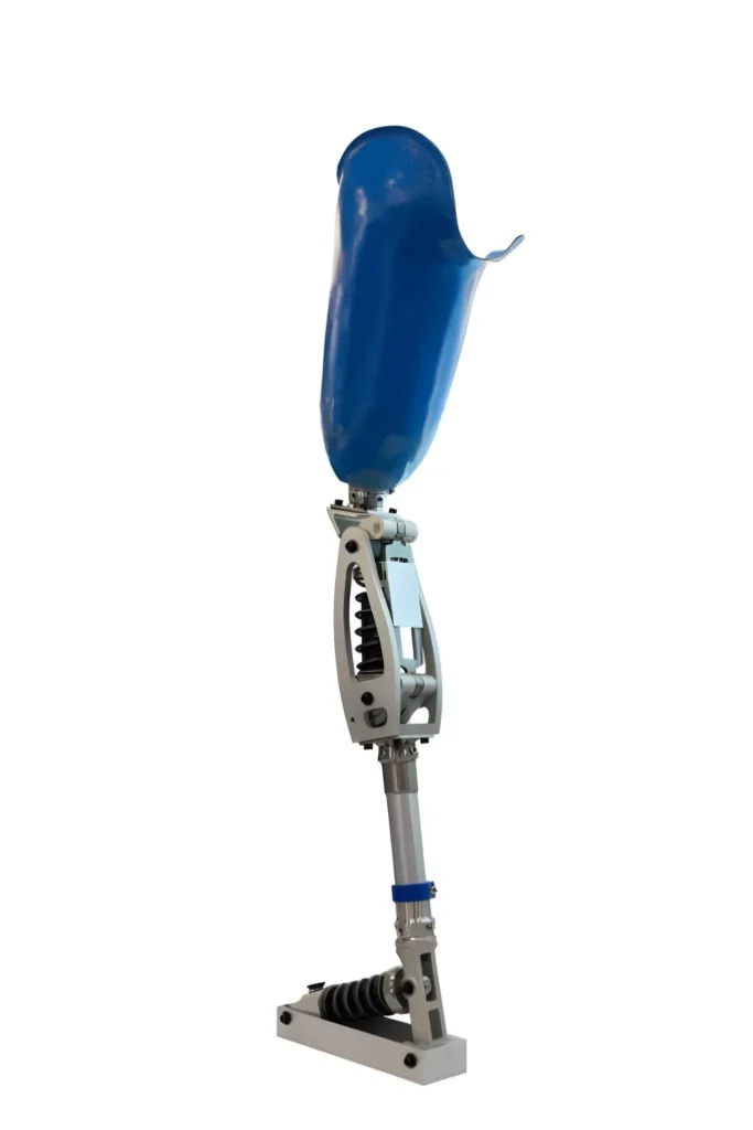
In robotics, titanium is used where moving parts require low weight and consistent stiffness. Side milling is used to maintain controlled geometry in load-bearing areas.
- Robotic arm joints with accurate side wall surfaces
- Structural links where deflection affects motion accuracy
- Mounting bases requiring stable alignment under repeated cycles
- Compact actuator housings where space and rigidity both matter
Key Takeaways
Titanium machining is used when parts need strength, low weight, and reliable performance under load. The main challenge is heat at the cutting zone, which affects tool life and cutting stability.
Good results depend on stable setups, rigid tooling, and controlled cutting parameters. If these are not managed, tool wear increases and accuracy drops quickly.
In practice, titanium machining is done at lower speeds with careful engagement to keep the process stable and predictable.
Get Titanium CNC Machining Support From Ydrapid
At Ydrapid, we provide custom CNC machining for titanium and other engineering materials like steel, aluminum, and engineered grade plastics like POM, PP, ABS, with over 20+ finishing options and full production assistance.
- Free DFM review before production to reduce machining risk
- Engineering support for design and tolerance optimization
- Material options include aluminum, steel, stainless steel, and titanium alloys
- Surface finishing options based on functional and cosmetic requirements
Contact us for custom titanium parts and machining solutions with engineering review and production support.

FAQ
What Makes Titanium Machining Expensive
Cost increases mainly due to slow cutting speeds and high tool wear. The heat concentration at the cutting edge decreases the tool life and thus, more tool changes and time are needed in contrast to aluminum or steel.
What Materials Can Replace Titanium in Some Applications?
Alternatives include aluminum and high-strength steel, which are normally found based on load and weight. Aluminum is utilized where weight is a critical factor, whereas steel is used when the cost-balance of weight and strength is more important.
What Should Be Considered Before Machining Titanium Parts?
Notable ones are tool rigidity, heat control, and stable fixturing. Good cutting parameters of titanium are that a poor setup or aggressive cutting will result in vibration, tool wear, and poor surface finish.
Why Does Titanium Require Special Cutting Conditions?
Titanium stores heat rather than dissipating it to chips when cutting. This heats the tools in a short period of time and impacts the tool life, and renders the process unstable in case of cutting conditions not under control.
What surface finishes are available for titanium parts?
Popular alternatives are bead blasting, polishing, anodizing (Type II and III), and passivation. However, the optimal choice depends on the part requirement, whether it needs corrosion resistance, appearance control, or lower friction.